30 watt LED Bench Light

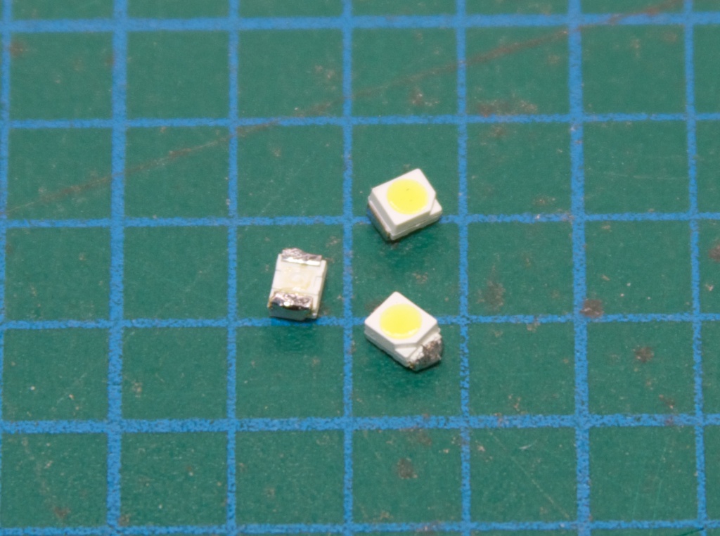
Several months ago I bought a set of 10W LED modules like this:

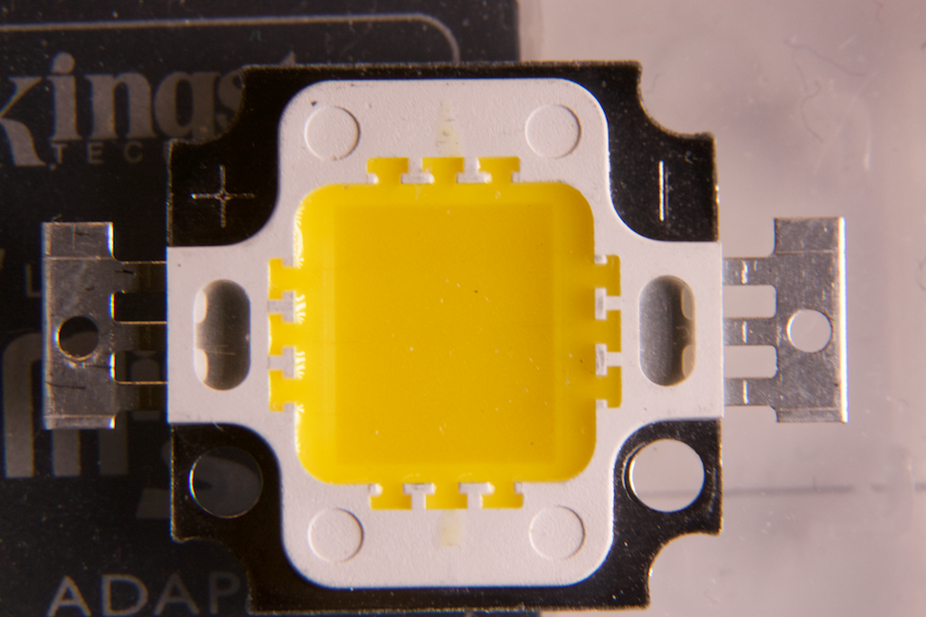
They have a multi-chip configuration, with an array of LEDs embedded in the center phosphor part. These units come in various voltages; the ones I got were ~30V. I designed a quick constant current circuit that runs off of a ~35VDC supply (open circuit, ~30VDC under load):

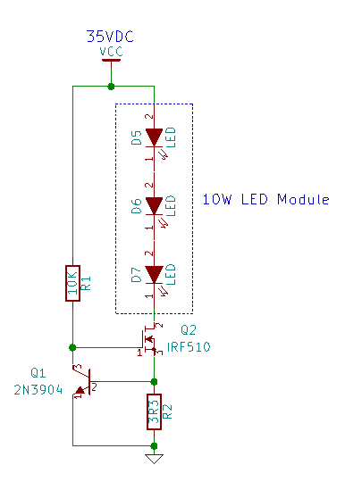
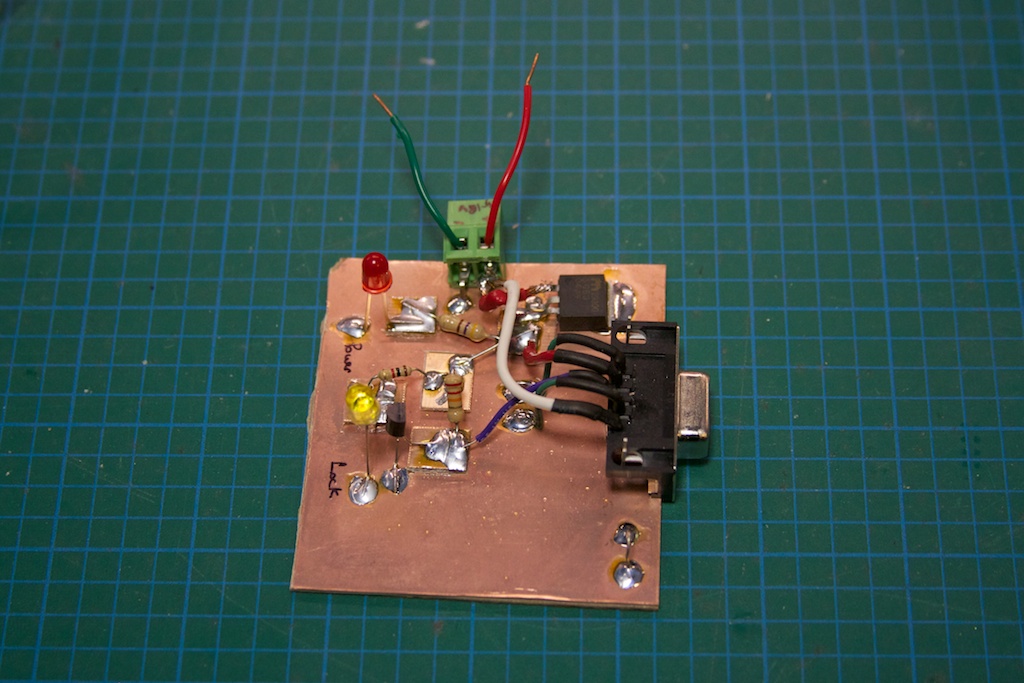
The constant current circuit is a simple N-channel MosFET with sense resistor feedback (using the 2N3904 to control the ‘FET). Knowing that there will be an ~0.6V drop between the NPN transistor’s base and emitter, we can calculate V=IR, or V/R = I, which gives us 0.6/3.3 = ~0.181A or 180mA through the LED module.

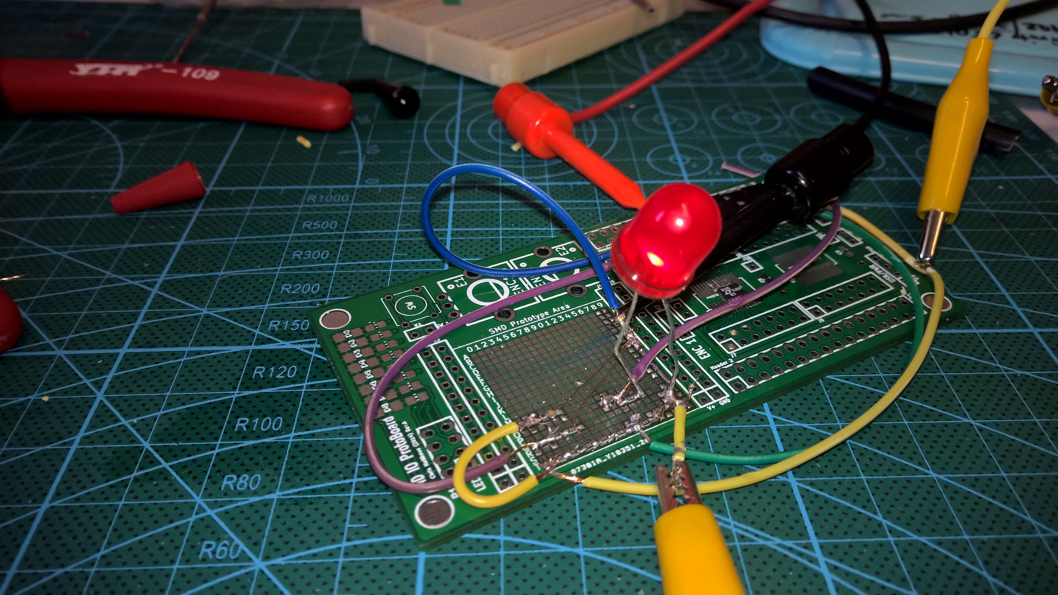
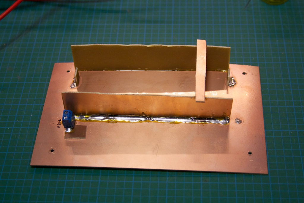
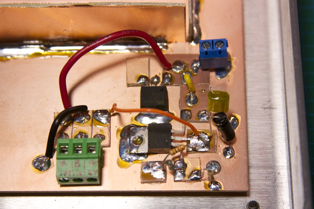
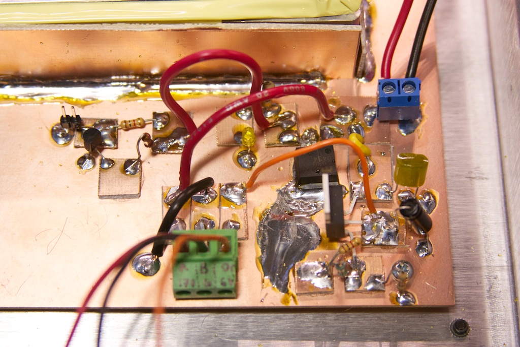
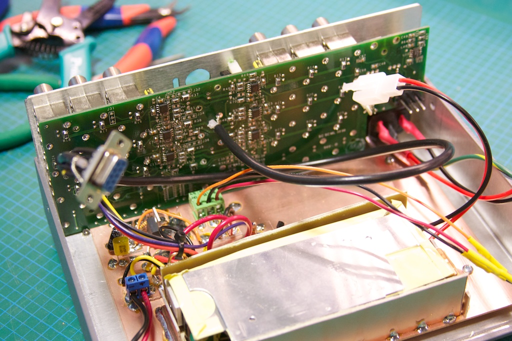
Here is a photo of the built circuit (there are 3 of them, one per LED module):

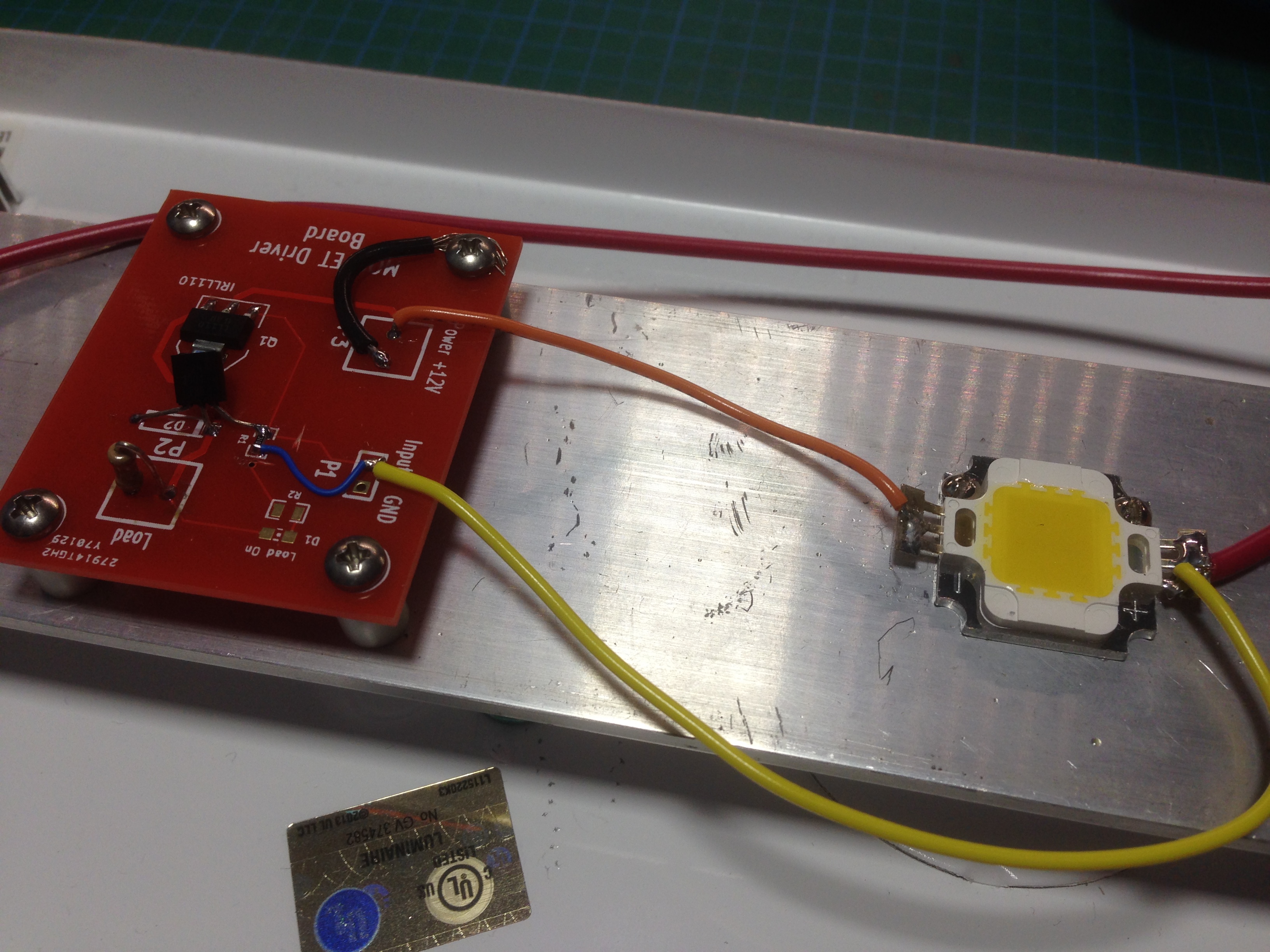
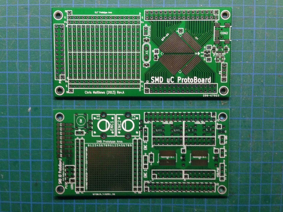
The PCB that I used was actually the first PCB that I ever designed, and it had an error so i never ended up using it. I modified the circuit on the PCB to accommodate the LED driver circuit above (reuse and recycle!).

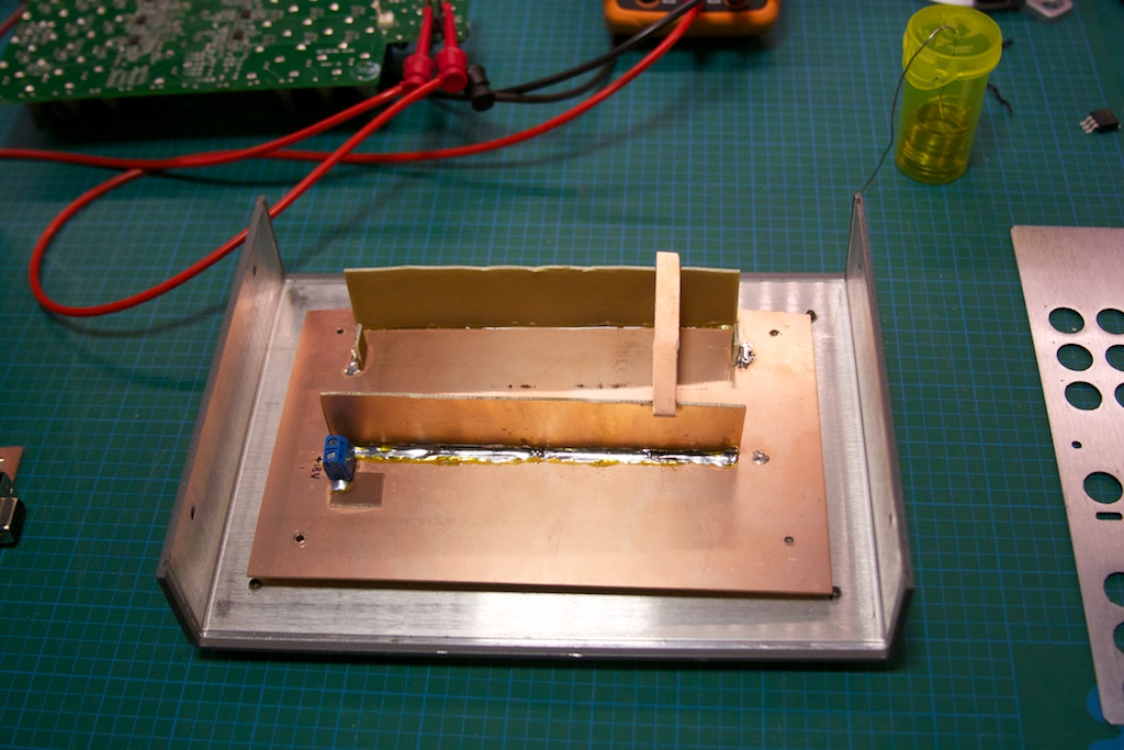
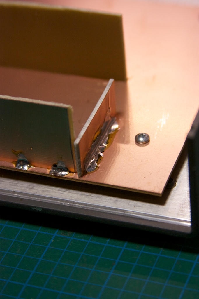
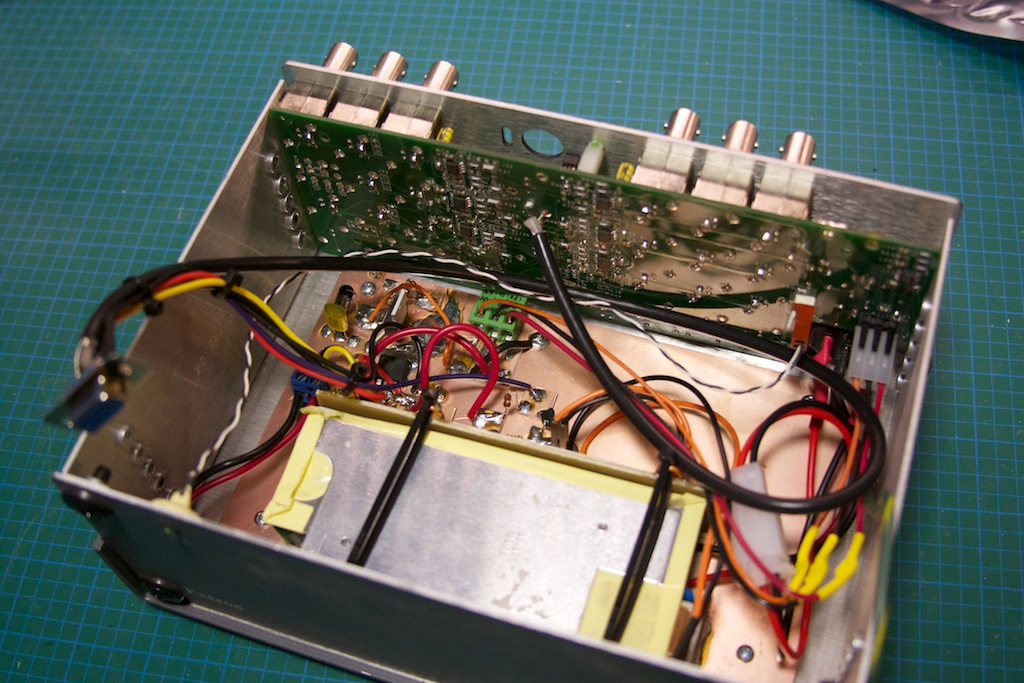
And from a different angle, showing the aluminum bar with the heat sinks under:

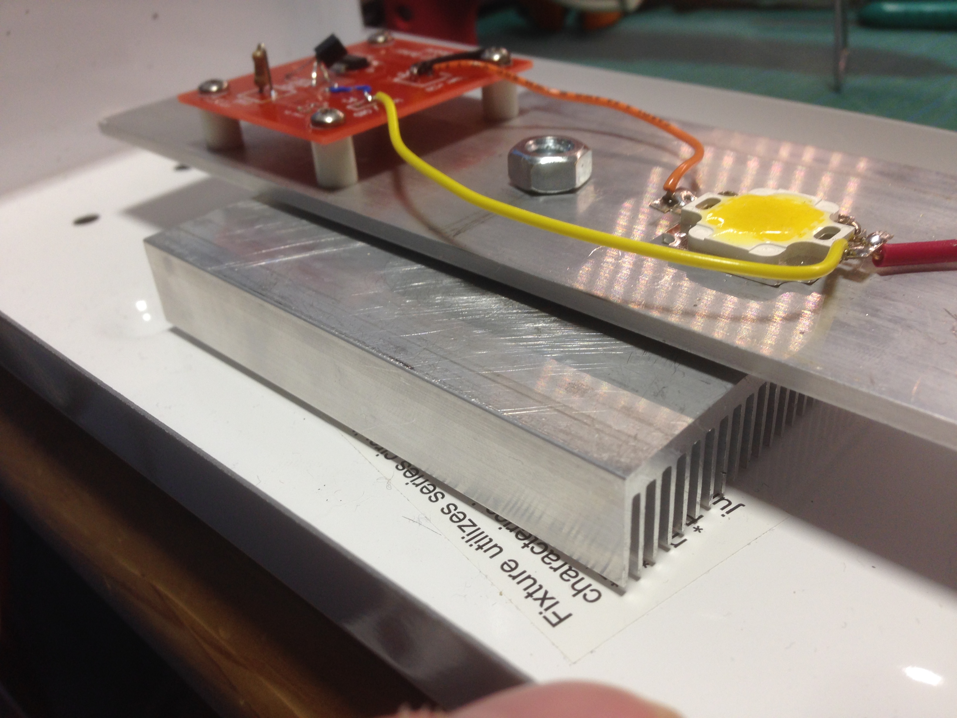
Originally I thought that it would be possible to thermal-paste and screw the main aluminum bar to the enclosure, but that didn’t work out too well in terms of height and clearances, so I added two big heat sinks (no idea what the specs are, they are “cheapie” ones from EBay). They do a good enough job, and the whole thing stays at a reasonable temperature as long as it is not left on for more than a few hours. Of note is that the heat sinks don’t make full contact with the aluminium bar; this will be fixed in the future, and I will be added a fan to the enclosure with some venting.

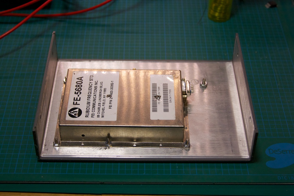
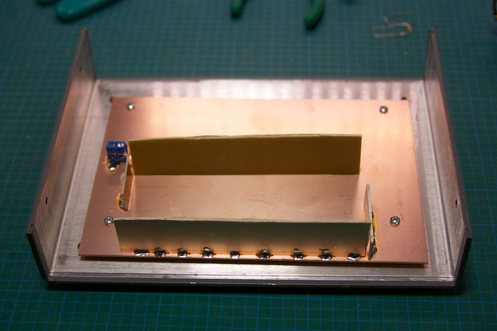
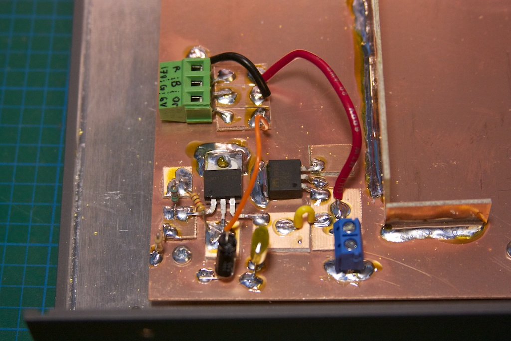
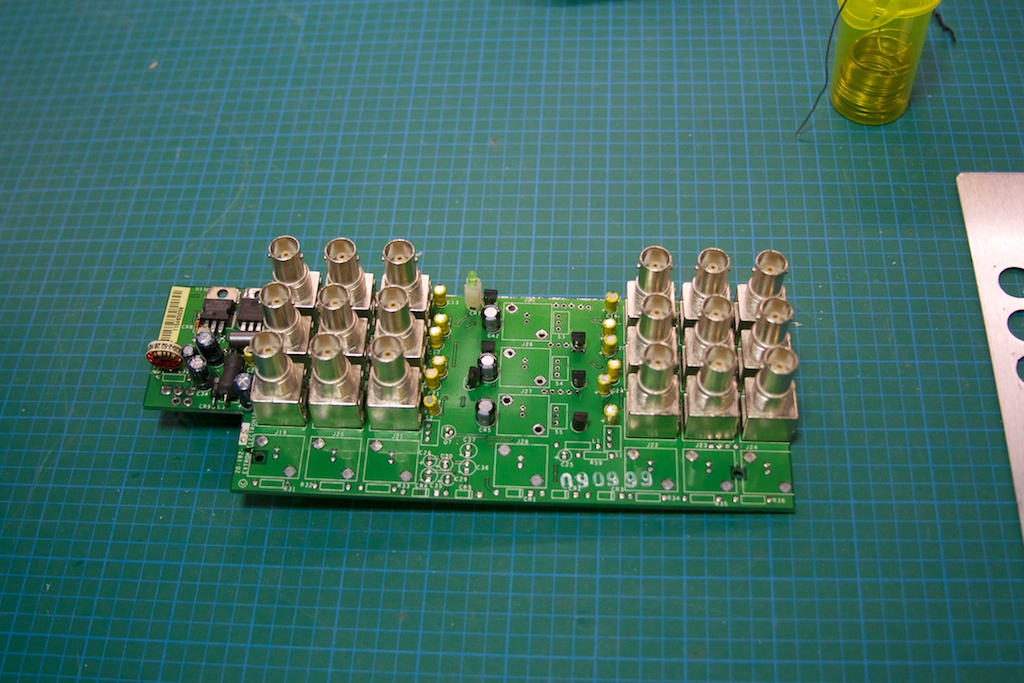
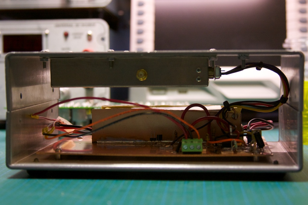
Here is a photo of the power input rectification and filtering board I put together:

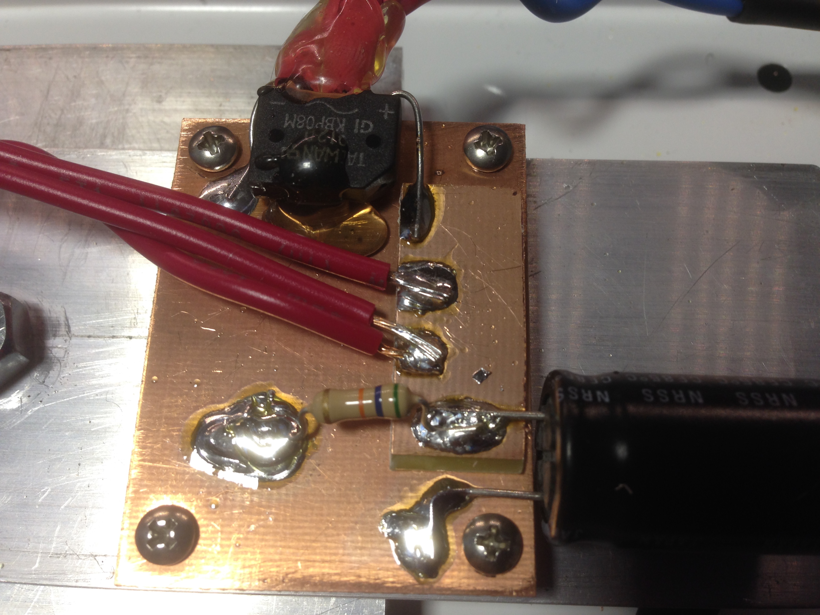
Note the 56 kΩ resistor soldered to the filtering capacitor in the foreground. I ran into a small problem that there was enough residual voltage across the capacitor after the lamp was turned off that caused some of the LEDs with lower forward voltage drops to stay lit. The resistor helps drain the capacitor quickly.

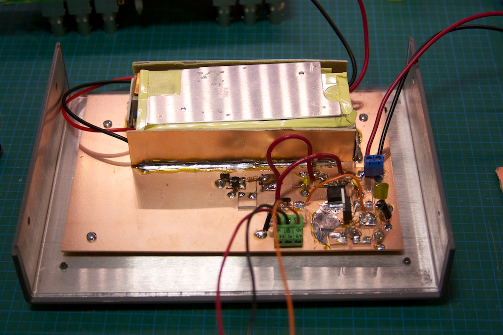
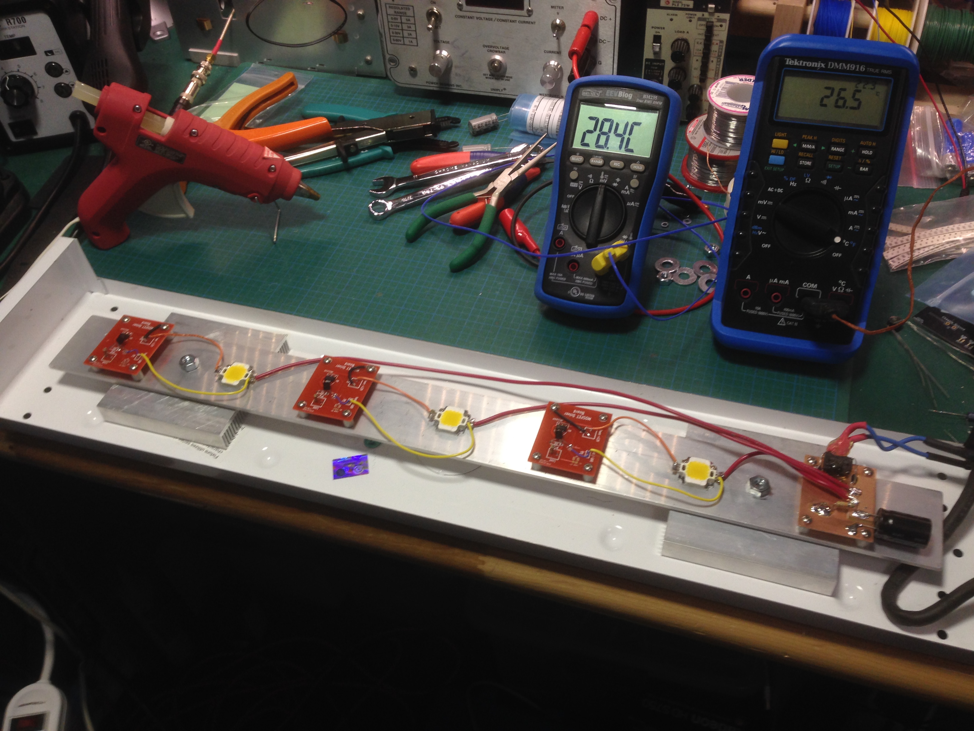
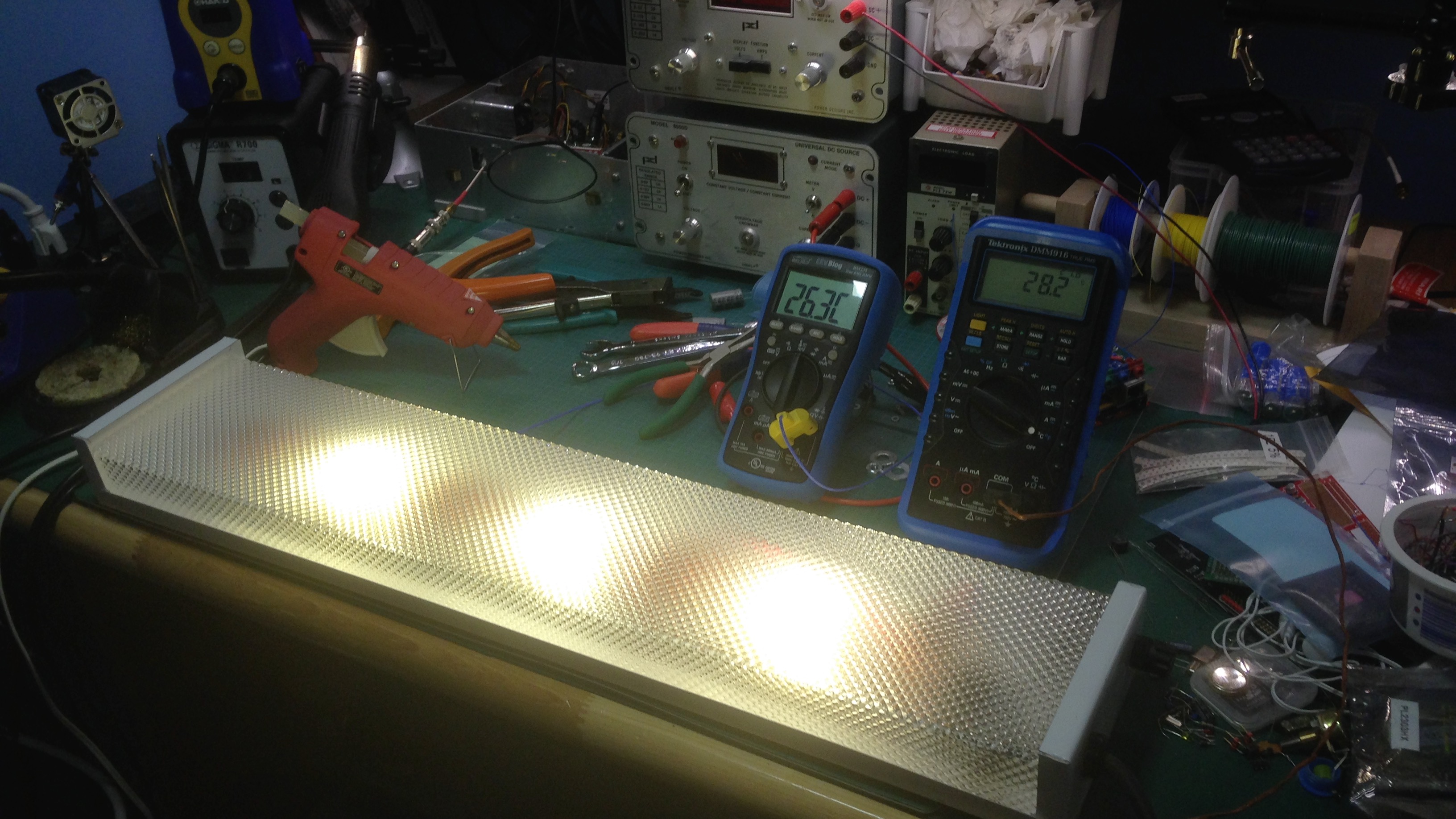
Here you can see the fully assembled unit on the electronics bench, plus a shot of it lit up during thermal testing:

And here is the final light mounted above my work bench in the garage:

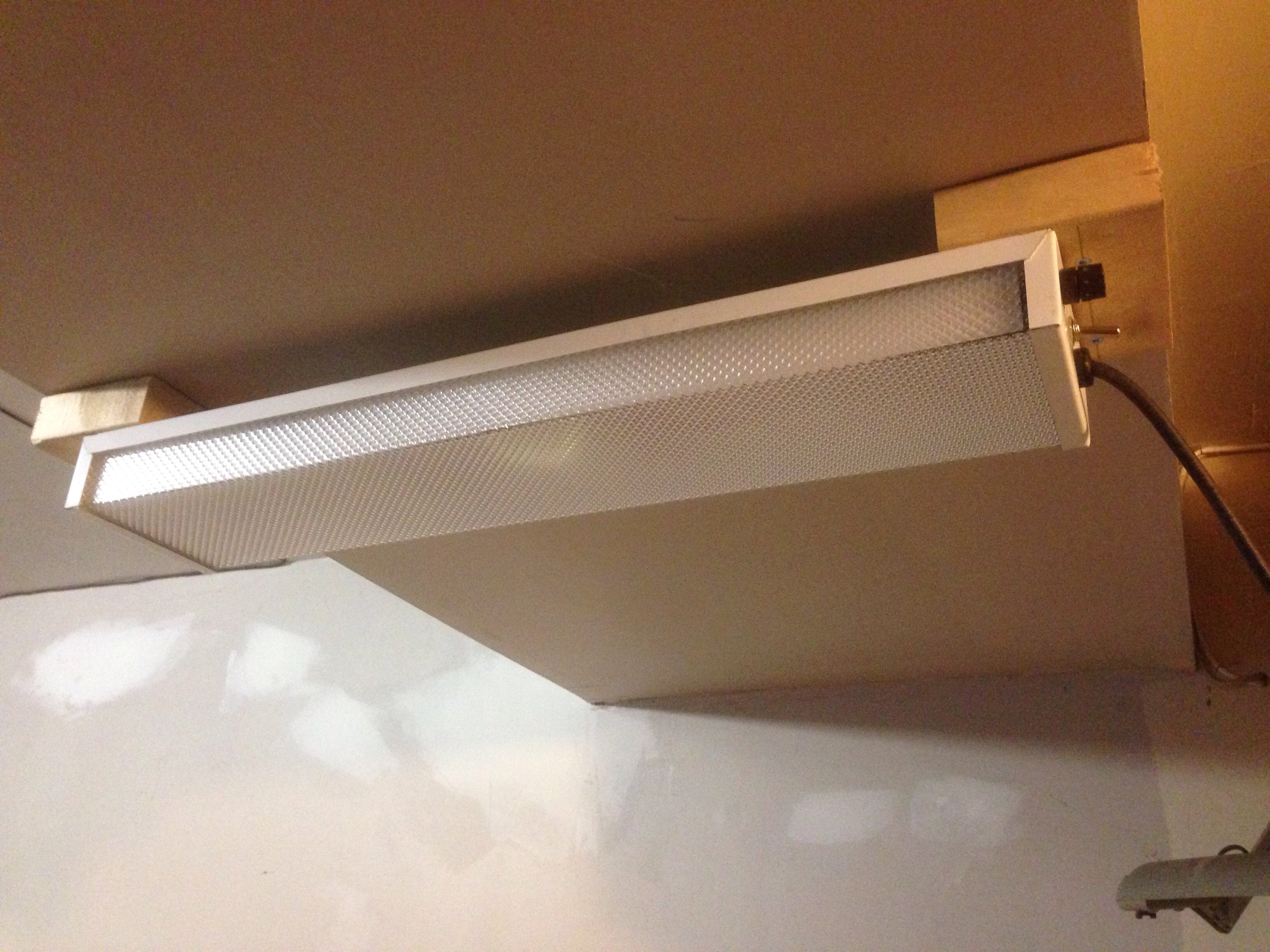
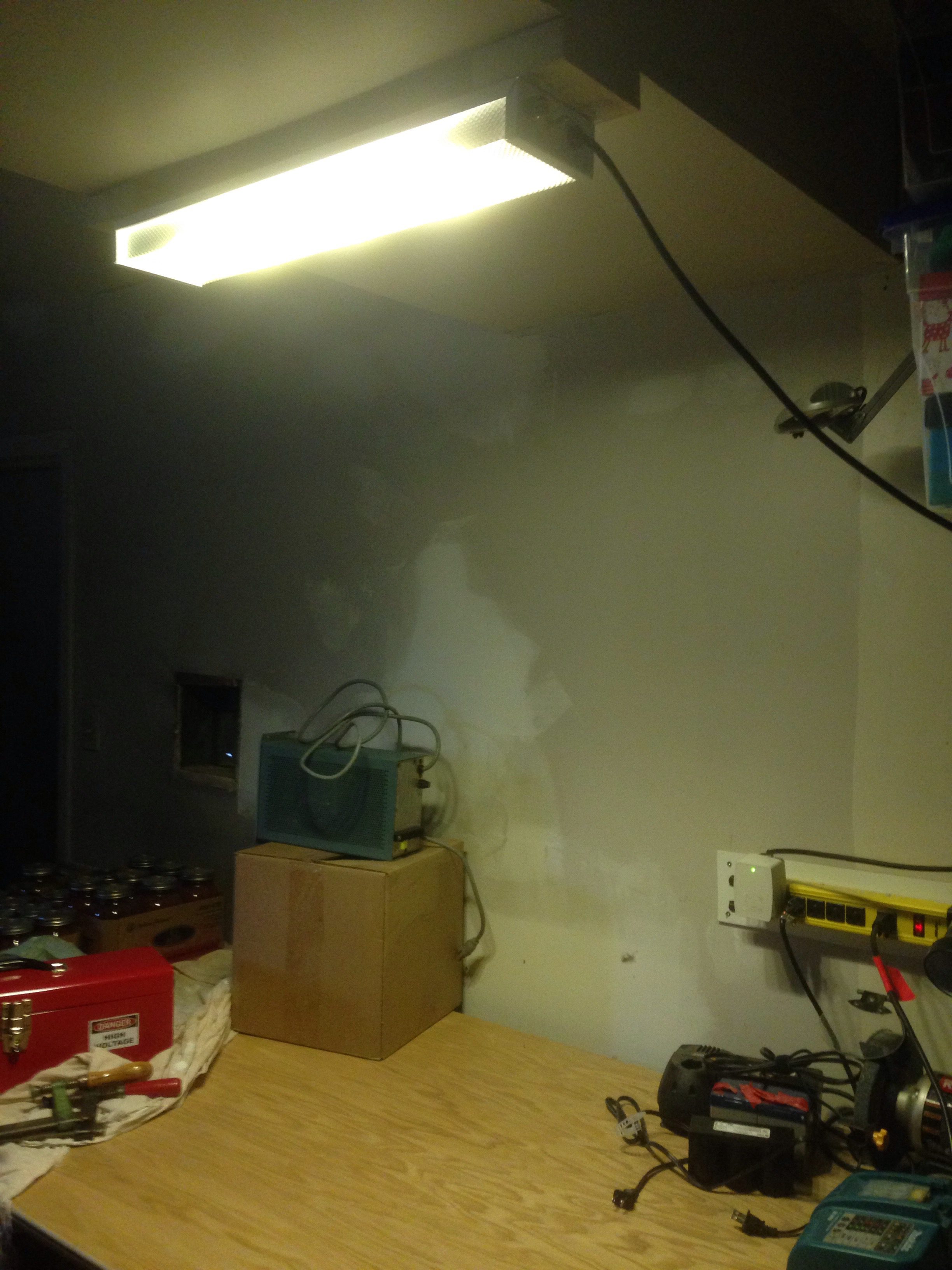
You can see in the back to the right the power bar with the AC adapter (right side of the power bar) that I used to power the light. It is a 24VAC unit (~27VAC without a load).

Measurements of the light output and power consumption will be performed and reported on in another post.

Frozen Privacy Screen Build

Last Christmas I decided to make my daughter her present. She had asked for a privacy screen that appears in the Frozen Fever animated short (only for a few seconds). I decided to go the “easy” route and build it out of pine wood and paint it.

The screen can be seen to the left of this scene:

For the design, I decided to go with a total height of about 4 feet (my daughter was 4.5 years old at this point, and about 3 feet tall). I wanted to get the domed tops of the panels looking similar, so I sketched something that looked about right on graphing paper:

Here you  can see a half arc (the top of the dome is on the right and the bottom on the left) which would then be mirrored to get the full dome. It looked about right so I proceeded to scale it up to full dimension and create a template:

Scaling the template involved measuring the distance from the center line of the half-dome to the curve of the dome. I then scaled both the distance from the mid-line out as well as the vertical position of the line to the full 12″ wood panel. The result of this was a fairly close enlargement of the dome’s curve onto a template sized for have the panel width, or 6″. After this was done I traced the template onto the 6″x4″x1/2″ pine boards I had bought (4 of them):

Cutting the boards was done using a jig-saw, but a band-saw (if available) would have yielded nicer results. As is, I did a fair amount of sanding to get the panels looking even and matched. The next step was to notch out the spaces for hinges (so the panels could fold up flat onto themselves for easy storage).


The tools used for this were a hammer and chisel.

Mark the panels that mate to each other right after cutting them or you will have a fun time trying to figure out how to get them to fit as cut later on!

The perfect hinge pocket is going to be a bit deeper than the hinge fastening sides, and this is because of the hinge joint, which is a bit taller than the two metal flanges. Also test and fit, since you will want to get adjust the depth a bit, and cut the second pockets a bit shallow and then keep testing as you deepen the second pockets to get a good matching fit that swings easily and without torquing the hinge at all.

Some assembly, paint and a really awful job at detailing (I need to work on that!) and voila, a Frozen inspired privacy screen!

A few things to note:

  • The screen panels are actually rather heavy, so this is not a great design for a little kid that is likely to bash stuff around or crash into it,
  • Detailing shapes on four separate panels is /HARD/, so practice before committing!
  • The bottom is never going to be perfectly flush, so the best method would be to assemble the panels as shown above before paint (before or after sanding) and cut them flush with a table saw or something (a circular saw would be fine as well, just use a guide!),
  • Height is a big consideration; ideally for a girl the bottom ends of the top dome shape should be about shoulder length, perhaps a bit higher.

PCBs in the Wild!

I have been working on a couple of prototyping boards for general “hey I need a PCB for this oh I have one here” type of projects. Since I’m working more with Surface Mount Technology (SMT) these days and have more of those part in my “stock”, I designed some prototyping boards with this in mind:

PMWVqK05NScwOySx7d_rqpRDDEQCtxBRgKVb5fMP5_Y

w8qOk0l8Cf6-VvLJCz_le5dyH_54Me0o0eiwX4rdkM8

I have sent a few of these to some people that I chat with on the #eevblog IRC channel, and one of them was kind enough to send me an “action shot” of a little LED-based project he used my PCB for!

WP_20150906_16_12_12_Pro

And another one from c4757p:

pcb-in-the-wild-2


Power Designs Inc 6050C Display Mod

Here’s a modification that I have been meaning to do for a while. It involved replacing the PCB in one of my power supplies with a modified version designed by me that upgraded the size of the 7-segment LED display.

IMG_5736

I ordered the board from OSHPark. My experience with them has been positive; the turn around time was about 2 weeks and the gold finish is very nice. I’m fine with the colour of the solder mask, however note that the mask is a matte finish rather than the typical “pearl” or “glossy” finish that I am accustomed to seeing on PCBs. Not a big deal, but something to think about. Also, the traces are a bit difficult to see through the solder mask.

IMG_5737 IMG_5739 IMG_5741

I of course did not fully check my notes when throwing together the schematic for this project which resulted in the boards I received having the ‘a’ and ‘g’ segments reversed. A few cut traces and a jumper wires later and all was working as expected.

IMG_5745 IMG_5744  IMG_5742IMG_5743

I originally tried to think of a better way of re-attaching the new display board to the existing display measurement/logic board, but in the end the simplest solution won out and  I just re-soldered the new display board back. The header pitch is 3.81mm and was a total pain to find (yay eBay!).

IMG_5746

The end result is a bright, clear and LARGER display. Here I have contrasted it with the model right after the 6050C, the 6050D which has a larger digital display (and also does not display the measurement mode as the 6050C does, E or I).IMG_5748If I decide to pick up any more of these supplies, I think I’d make the same display modification to them as well. I have been looking at the 6050A models (which can usually be had for cheaper): these might also be good for a “digital makeover” involving removing the analog meter and designing a new digital display PCB.


Tektronix DMM 916 Back-light Mod

In keeping with the theme of back-light mods, I have another one here for you all. Recently I was able to get my hands on a well-loved (read: had the piss kicked out of it) Tektronix DMM 916. The specs are nice:

  • 4.75 digits
  • 40,000 count
  • Basic DC accuracy of 0.06%+1 count

The only problem which I didn’t know until I got the meter in my hands was that the back light was horrible:

IMG_5669

Wait, where is that back-light?IMG_5671

Still can’t see it? Turn off the lights!IMG_5670

I’m not sure if this is “factory standard” or just a sign of the age of the unit, but either way it needed some change. The first thing I did was to open up the meter and check out the display:

IMG_5675

There is a small slot on one side of the display assembly where the lamp bulb pokes into the light pipe. At first I thought I might use a standard through-hole LED, but realized that I wouldn’t be able to mount it without either cutting the trace (for the limiting resistor) or cutting the display. I didn’t want to mod the board, in case I or someone else wanted to restore it back to a incandescent bulb. So I choose to use a SMD chip LED and resistor, and build it “tee-pee” style on the top of the display PCB, so that the LED and resistor would stick up vertically into the display light-pipe recess:

IMG_5679

The LED is blue, Digikey part number 475-2816-1-ND with a 270ohm current limit resistor. The bulb sank about 20mA while the LED uses ~18mA, so a bit more efficient. I’m still not sure about the blue, but I figured it matches the theme of the case, so why not:

IMG_5680

And as is evident, it is much brighter even with the lab lights on. Curiously, it is not much more legible in the dark in terms of the digits on the screen as I would have thought.

HP8642B Signal Generator Mod

A quick mod post here. I saw this post by Kerry Wong, and having the same hardware myself (and finding the backlight ridiculously dim) I thought this mod was a great idea and wanted to try it myself. First, here is a shot of the original backlight:

HP8642B-OrigBL

I pulled the front panel apart, and decided to use white SMD LEDs for my replacement mod:

IMG_5664

After soldering up everything and reassembling (and of course cursing a lot due to the number of defective white LEDs that I didn’t realize that I had), the result is beautiful!


HP8642B-Mod

And here is the same Easter egg that Kerry found (hold down the MSSG key while powering on the unit):

HP8642B-ModBL1


Lab Frequency Standard

I’ve been rather silent for a couple of months now, but I have been busy! This time it is a laboratory frequency standard! This project is modeled on the work done by Gerry Sweeney over on his blog. I have been assembling the various pieces needed for this build for several months now, and just recently decided to take the plunge and do the build.

It started off with a Rubidium frequency standard from Frequency Electronics, the FE-5680A. These can be purchased used off of EBay for ~120$ CAD. Buyers beware: I had success with my first unit, but others have not been so lucky. There are numerous configurations of this unit, with various features present or missing, including the 10MHz sine output. This project requires at a minimum the 10MHz out. Some units will have this via a dedicated BNC or SMA connector, others (like my unit) will have it present on a pin from a DB-9 connector.

The second most important component is the case which will house the completed project. I was originally going to choose a basic project box, but Gerry was pointed towards a distribution amplifier for video. Since the signal from the FE-5680 would need to be replicated on multiple outputs to be useful, some sort of amplifier was going to be needed. It just so happens that 10MHz lies in the range of off the shelf video amplifiers, and the model I got by Extron, the ADA 6 Component was perfect for the job AND was only 40$ on EBay.

Other than just putting the Rb standard in a box with a bunch of outputs, I wanted to have an indicator LED that lit up when the Rb was locked on 10MHz. My particular unit will pull a pin on the DB-9 connector LOW when the Rb is locked. A quick transistor circuit with a regulator feeding off a 17V supply and I had a small prototype board completed:

IMG_5579

Once I had the “interface circuit” figured out, I started laying out what the mechanical construction of the project would look like. I decided to use the case itself as a heat-sink and seeing as how the Rb standard likes to be warm (haha, non-heat-sinked, the case measures ~65C), I decided to mount it to the top half of the box:

IMG_5577 IMG_5578

The Rb standard requires 2 different power inputs: 5V and15-18V. The distribution amplifier also required 2 different power rails: 6.2V and 17V. I decided that the easiest way to power it all would be to pick up a 18.4V laptop power brick, rip the guts out, and add a LM317-based regulator to get the 6.2V to my existing interface circuit. I discovered that the Extron was actually using the 17V rail to power a buck converter-inverter circuit, so the 18.4V input didn’t change it too much.

IMG_5580 IMG_5581 IMG_5585 IMG_5587 IMG_5588 IMG_5589 IMG_5590 IMG_5591

I wired up a small wiring harness to go from the Rb standard’s DB-9 connector to the various parts of the interface board. I then modified the amplifier board to change the input/output impedance from 75ohm to 50ohm:

IMG_5582

Not having any 50ohm resistors handy (and they’re damn expensive as well!), I used 2 100ohm resistors in parallel stacked on top of each other:

IMG_5584 IMG_5583

I soldered in the coax to the center channel, and then jumped the signal from the center channel to the 2 other ones with some wire. This means I will have a total of 18 10MHz outputs on this standard 🙂

The testing and assembly:IMG_5593 IMG_5597 IMG_5598 IMG_5600 IMG_5601

I ran into one problem when testing, which was a deformed lower part of the sine wave on the outputs (all of them). You can see it on the oscilloscope to the upper right:

IMG_5602

I started probing around (“THOU SHALL CHECK VOLTAGES!”), and discovered that the negative rail to the op-amps was running at ~0.3V, which was not right. Running back through the circuit on the amplifier board I realized that I had flipped the 6.2V and 17V rails on the input connector after splicing it into my interface board. After switching them back, everything was working as expected!

IMG_5604

Turns out my frequency counter on the upper right is probably off by 0.5 Hz… not too shabby. There are a couple of things that need to be done: adding a heat-sink to the top of the case for extra dissipation and adding some passive ventilation holes on the top/back of the case and on the bottom.

Another Nixie!

I found the first Nixie-Tube clock that I built from a kit so awesome, however the only problem was that it got requisitioned for the living room! So of course I had to order another one for my office.

Again, Pete from PVElectronics did a great job on getting the clock kit to me, and assembly went smoothly. Towards the final stages of the build, there is a step that tests all the tubes, the micro-controller and the high voltage generator with a test pattern that counts up from 0 to 9 and then cycles over. It was at this step that I ran into a weird issue where all of the tubes would display all digits when they should have been displaying 4 or 8. I finally isolated the problem to a single tube (although why it would affect all tubes was unclear at this point):


After Pete and I scratched our heads for a few days, we finally came to the conclusion that it must be some sort of internal short in the actual tube (weird!). He promptly mailed me a new tube + circuit mounting board and I was back in business and finished the clock:


And the color cycling:


And here are a few build pictures I took along the way:

IMG_0265 IMG_0268 IMG_0278 IMG_0279 IMG_0281 IMG_0282


And some shots of the questionable tube:


IMG_0290 IMG_0291 IMG_0292 IMG_0293 IMG_0294 IMG_0296 IMG_0297

And the test/debugging setup that I put together.  Here (and I’ve said this before) I’m using two of the test points on the board. I have soldered in two single-pin sockets so I can easily attach a breadboard/other test components to the live board:

IMG_0306 IMG_0307 IMG_0308 IMG_0309 IMG_0310

And the case being assembled:

IMG_0276 IMG_0277