USB to Serial Adapter Project

Not satisfied with the “typical” USB to serial cables that one can readily buy, I decided to design my own.  The basic reason was just another excuse to practice designing a circuit and laying out a printed circuit board (PCB), but to also create a very small unit that can be easily transported. I additionally wanted to have some sort of visual feedback of data transfer over the adapter, so two LED’s (receive and transmit) will address that.

The circuit design came from the application notes on the FTDI chip that I am using, the FT230X:

USB2Serial

I did a few tests with a bread-boarded version of this circuit. You will notice that there are 2 bread boards; the bottom one has the USB to serial circuit, the top one has an Atmega8 micro-controller with a some program that echoes back characters it receives on its serial interface (used for testing):

IMG_5304


A close-up of the USB to serial circuit:

IMG_5308

And the two circuits/bread-boards separated:IMG_5307

The other requirement was size: that whole circuit will need to fit within this little box:

IMG_5309

I have actually laid out the board, and so will be finalizing it in the coming days. I will write up another post with the board layout, 3D shots and a bill of materials. In terms of price, this will not be saving me any money over buying a pre-built adapter.

Electronics gear, Part 1 – The Meters

After spending both a bit of time and money, I have assembled a set of tools both new and used to help me on my path to learning a bit about electronics. This first post will be about the most basic of tools for any individual that is interested in electronics, the multimeter.

Agilent U1232A

Originally I was going to buy 2 meters, one high quality one for my primary meter and a secondary one for measuring simultaneous current or an additional voltage. To this end I purchased an Agilent U1232A (6000 count, basic DC accuracy of 0.5% + 2 counts) to use as my primary calibrated meter. I bought it at Active Tech for 150$ + shipping, and it came with a certificate of calibration. This was important to me so I would have some confidence when I test any other meters against it to see if they are calibrated. I have attached 3 shots of the meter measuring 100 ohm, 1K ohm and 10K ohm resistors (0.1%):

IMG_5294 IMG_5296 IMG_5293


Hewlett Packard 3478A

The second meter I picked up on Ebay for ~100$ + shipping. I was originally going to try and find another decent hand-held meter, but after seeing a review of the HP 3478A, I decided that I wanted to get a high-precision 5 1/2 digit (30000 count!) bench top meter. It can be found cheaper (I have seen it listed for 60$, but the auctions usually finish higher) but I figure if you can pick this bad boy up for less than 200$ shipping in, you’re doing good. This meter is old but an excellent purchase as the accuracy (as far as I can measure and test) is spot-on when compared against the Aglient meter. The basic DC accuracy of this meter is +/- 0.02% + 2 counts. Again, I have attached some shots of the HP meter measuring the same resistors as above:

IMG_5288 IMG_5290 IMG_5291

You will note that I used the 4-wire measurement function of this meter to measure these resistors. This allows the meter to remove any resistance from the test leads themselves (which ended up about a 2.5% error). Also, you may have noticed the “non-standard” test probe connector for the current measurement on the bottom right of the meter face: this was due to a the fuse holder/connector piece being missing (something I hadn’t noticed in the pictures of the meter on Ebay). I looked around, but even these HP meters being sold “for parts” were 100$+ and Agilent does not stock this part any more. I hacked on a binding post with a 3A fuse behind it and that solved that! So beware: when looking for this meter on Ebay or any other second-hand site, MAKE SURE you get the current socket + fuse holder!


Fluke 27/AN

The last meter that I picked up on Ebay is a Fluke 27/AN for ~70$ + shipping, although it can be found cheaper: I have seen them for as low as 50$ for this version.  It is the “worst” of the three: a 3200 count instrument, +/- 0.1% + 1 count basic DC volts accuracy. So it is more accurate than my Agilent (in theory) but has less resolution than the Agilent. The reason I bought this meter was to have a nice solid, built like a tank meter that I would be confident enough to use with mains testing (if need be) and would be rugged enough to use outside the “lab” environment. It also has a 10A current range, which is handy (since the HP can only handle a maximum of 3A). With a rated 900 hour battery life, this meter is the one that I would trust to be working when I need it. Below are some shots of the same resistor measurements as above:

IMG_5299 IMG_5297 IMG_5298


As a final test, here is a shot of all three meters connected to the same power source (DC voltage). As you can see, they are all almost exactly the same (of course the HP will have the most resolution, so we can ignore the least significant digits):

IMG_5285

All in all, for a couple of second-hand meters, I am very pleased with the overall accuracy (assuming that the Agilent I have is reasonably well calibrated, since I am using it as a transfer standard). I do not have a meter that can measure temperature, so that might be the next thing to look for!

MOSFET Driver Board, Rev C

It is said that one should learn from one’s mistakes. In the process of learning how to design and get a Printed Circuit Board (PCB) manufactured, I have indeed made a few mistakes. I would like to share them with you here.

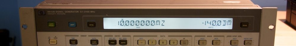
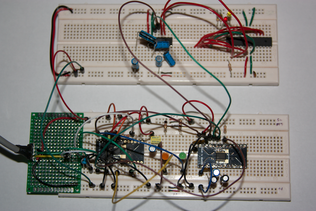
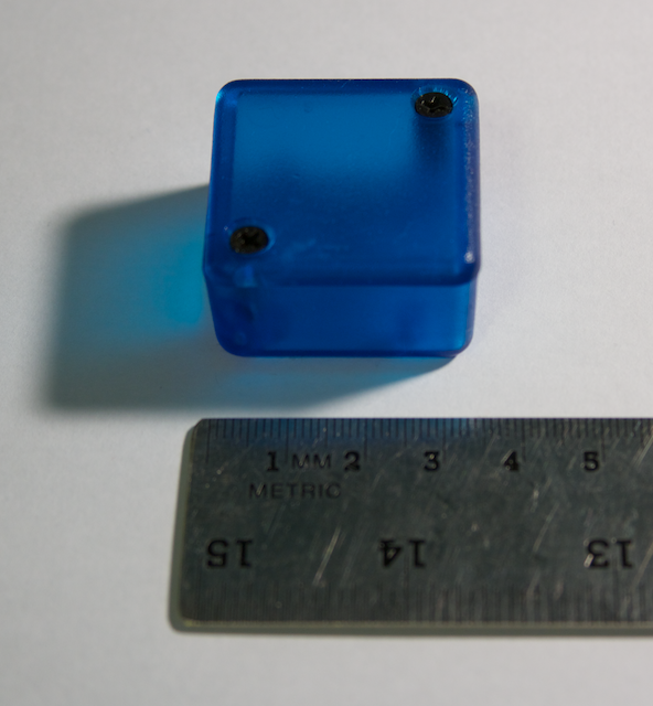
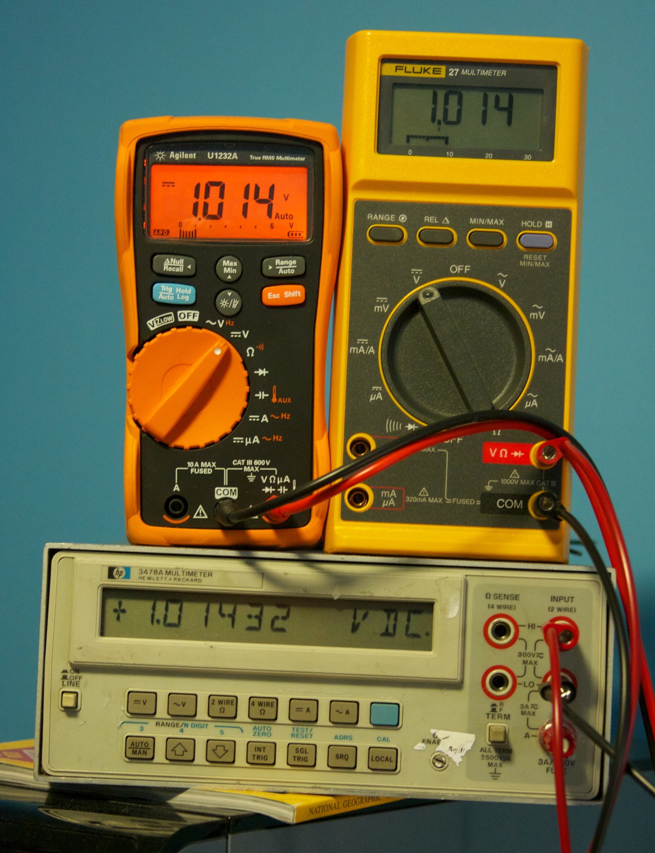
First, a quick update on the board that I was designing. My requirement was to be able to drive a spinning light assembly (pictured below) from a micro controller (MCU). Rather than use the traditional relay-based system (which would use a transistor to achieve MCU control) I decided to design it using a MOSFET (a big ‘ol voltage-controlled switch). I also figured that this would present a good opportunity to learn how to design and lay out a very simple PCB.

Always, ALWAYS, Double-Check Your Work

I don’t know if I can emphasize this more: a core theme in all of my mistakes during this project have been due to this. My first board, Rev ‘A’, suffered from a major circuit design error that occurred when I moved my circuit design from the bread board to the schematic CAD tool (I got the circuit backwards: I needed one that worked with a “NPN” transistor, but designed one that worked only with a “PNP” transistor).

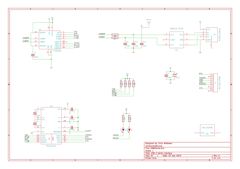
Here is my awesome not working circuit (Rev A):

MosfetDriverBoard-RevA

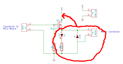
Here is the corrected circuit with the motor BEFORE the NPN MOSFET:

MosfetDriverBoard-RevC

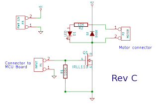
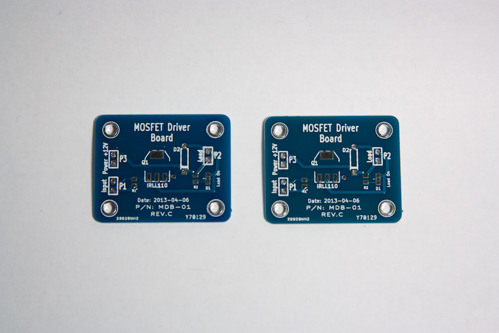
My second revision, Rev ‘B’, was not manufactured; it had the corrected circuit design, but I wanted to tighten up the physical PCB layout so I created Rev ‘C’:

IMG_5160

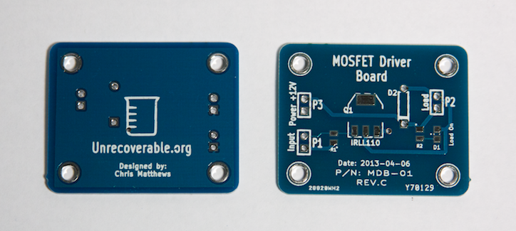
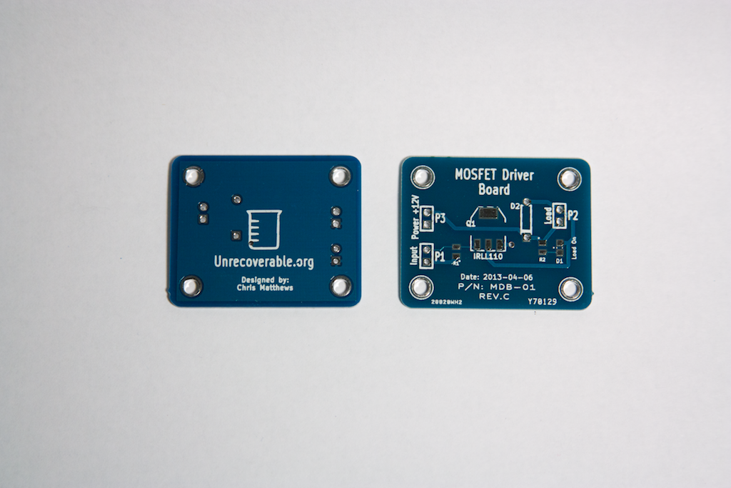
I had this revision manufactured. The mistake that I should have caught on this time was the adjustments I had made to the hole diameters for the terminals (for the inputs and outputs); I had forgotten to adjust the copper (called “annular ring”) around the holes to make them larger as well. This wasn’t a show stopper, as I was able to solder the components on the board still, but it was borderline.

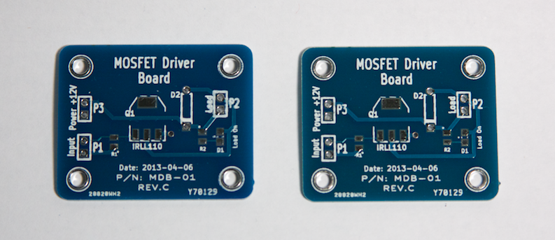
As an aside, I noticed that the front solder-mask (the blue color) was not uniform between boards; some were blue and others were slightly blue-greenish, about half and half. I also noticed that the silk-screening was less than awesome on all the boards. Note that this board was Hot Air Solder Leveled (HASL) and NOT gold plated like the first revision board.

IMG_5158


Thou Shall Check The Data Sheet. Again.

The second biggest mistake that I made was not re-checking the foot prints (the “physical” sizing of a component) during and after I completed the layout of the PCB. DO THIS. It avoids embarrassing mistakes such as holes that are too small to fit the leads of a through-hole component. You should also re-check the pad/leads in the data sheets to make sure they fit with your component symbols and circuit design. Don’t assume anything!

Always Have a Reason

When you place a component, connect a trace, add a connection, always have a reason for doing so! This will prompt you to ask yourself why you are doing this and perhaps lead you to discover a mistake in the making.

Test Points

This board was a bit too small to warrant test points (PCB pads that are designed specifically to be accessible to probes for testing properties of your circuit) but remember to think about adding them in. This can make debugging a malfunctioning circuit much easier later on. Also remember that it may be a good trade-off when designing a prototype device to take a little more space but offer debugging facilities such as test points and wire jump points.

Remember To Add Your Name!

If you truly are happy with your design and PCB layout, then you won’t mind putting your name, date, revision information and other useful identification information on the PCB. Do it! This will make differentiating board revisions easier as well as identifying you as the designer. Take some credit!