Macro Rings and Test Shots

I’ve been into photography for many many years. A long time back, when I first started, I acquired a macro lens. This was essentially a regular lens but with an adjustable bellows on it. I have not had any kind of macro lens since then, and now that I’m getting back into documenting some of the work that I’m doing in electronics, I decided to “spring” for a set of macro rings:

IMG_5772

And this is what they look like attached to a lens:

IMG_5773

(you can use any lens; the focal length of the lens used will make a difference on the magnification that you end up getting)

And a couple of test shots I took with the rings:

IMG_5770 IMG_5769

Power Designs Inc 6050C Display Mod

Here’s a modification that I have been meaning to do for a while. It involved replacing the PCB in one of my power supplies with a modified version designed by me that upgraded the size of the 7-segment LED display.

IMG_5736

I ordered the board from OSHPark. My experience with them has been positive; the turn around time was about 2 weeks and the gold finish is very nice. I’m fine with the colour of the solder mask, however note that the mask is a matte finish rather than the typical “pearl” or “glossy” finish that I am accustomed to seeing on PCBs. Not a big deal, but something to think about. Also, the traces are a bit difficult to see through the solder mask.

IMG_5737 IMG_5739 IMG_5741

I of course did not fully check my notes when throwing together the schematic for this project which resulted in the boards I received having the ‘a’ and ‘g’ segments reversed. A few cut traces and a jumper wires later and all was working as expected.

IMG_5745 IMG_5744  IMG_5742IMG_5743

I originally tried to think of a better way of re-attaching the new display board to the existing display measurement/logic board, but in the end the simplest solution won out and  I just re-soldered the new display board back. The header pitch is 3.81mm and was a total pain to find (yay eBay!).

IMG_5746

The end result is a bright, clear and LARGER display. Here I have contrasted it with the model right after the 6050C, the 6050D which has a larger digital display (and also does not display the measurement mode as the 6050C does, E or I).IMG_5748If I decide to pick up any more of these supplies, I think I’d make the same display modification to them as well. I have been looking at the 6050A models (which can usually be had for cheaper): these might also be good for a “digital makeover” involving removing the analog meter and designing a new digital display PCB.


Tektronix DMM 916 Back-light Mod

In keeping with the theme of back-light mods, I have another one here for you all. Recently I was able to get my hands on a well-loved (read: had the piss kicked out of it) Tektronix DMM 916. The specs are nice:

  • 4.75 digits
  • 40,000 count
  • Basic DC accuracy of 0.06%+1 count

The only problem which I didn’t know until I got the meter in my hands was that the back light was horrible:

IMG_5669

Wait, where is that back-light?IMG_5671

Still can’t see it? Turn off the lights!IMG_5670

I’m not sure if this is “factory standard” or just a sign of the age of the unit, but either way it needed some change. The first thing I did was to open up the meter and check out the display:

IMG_5675

There is a small slot on one side of the display assembly where the lamp bulb pokes into the light pipe. At first I thought I might use a standard through-hole LED, but realized that I wouldn’t be able to mount it without either cutting the trace (for the limiting resistor) or cutting the display. I didn’t want to mod the board, in case I or someone else wanted to restore it back to a incandescent bulb. So I choose to use a SMD chip LED and resistor, and build it “tee-pee” style on the top of the display PCB, so that the LED and resistor would stick up vertically into the display light-pipe recess:

IMG_5679

The LED is blue, Digikey part number 475-2816-1-ND with a 270ohm current limit resistor. The bulb sank about 20mA while the LED uses ~18mA, so a bit more efficient. I’m still not sure about the blue, but I figured it matches the theme of the case, so why not:

IMG_5680

And as is evident, it is much brighter even with the lab lights on. Curiously, it is not much more legible in the dark in terms of the digits on the screen as I would have thought.

Signal Generator

This is an acquisition that I purchased earlier in the year (a great bargain off EBay!).

IMG_5570

I decided to have a look inside it (not having any clue what goes into a function generator of this caliber.

IMG_5569 IMG_5572

Nice idea of putting the wiring schematics on the cover of the unit, as that way one can always figure out how to put the whole thing back together. And then I saw this:

IMG_0807

Wow.  So I decided to save a deeper dive into the unit for a later date. I built a stand for the generator and called it a day.

IMG_5574 IMG_5576 IMG_0810 IMG_0809

Electronics gear, Part 1 – The Meters

After spending both a bit of time and money, I have assembled a set of tools both new and used to help me on my path to learning a bit about electronics. This first post will be about the most basic of tools for any individual that is interested in electronics, the multimeter.
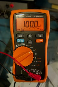
Agilent U1232A

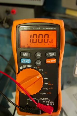
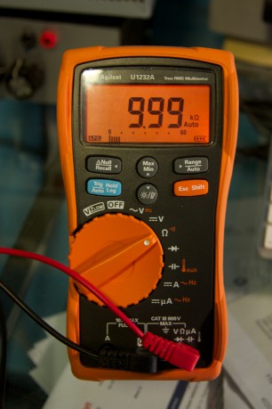
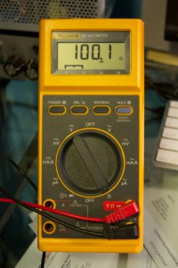
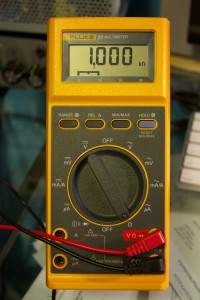
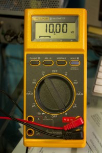
Originally I was going to buy 2 meters, one high quality one for my primary meter and a secondary one for measuring simultaneous current or an additional voltage. To this end I purchased an Agilent U1232A (6000 count, basic DC accuracy of 0.5% + 2 counts) to use as my primary calibrated meter. I bought it at Active Tech for 150$ + shipping, and it came with a certificate of calibration. This was important to me so I would have some confidence when I test any other meters against it to see if they are calibrated. I have attached 3 shots of the meter measuring 100 ohm, 1K ohm and 10K ohm resistors (0.1%):

IMG_5294 IMG_5296 IMG_5293


Hewlett Packard 3478A

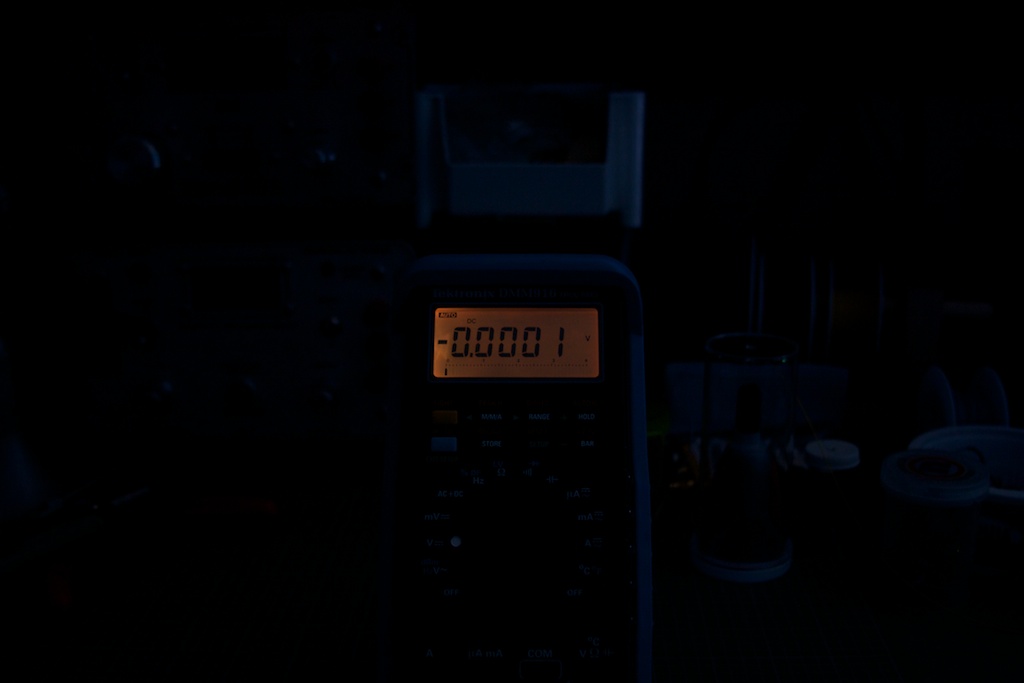
The second meter I picked up on Ebay for ~100$ + shipping. I was originally going to try and find another decent hand-held meter, but after seeing a review of the HP 3478A, I decided that I wanted to get a high-precision 5 1/2 digit (30000 count!) bench top meter. It can be found cheaper (I have seen it listed for 60$, but the auctions usually finish higher) but I figure if you can pick this bad boy up for less than 200$ shipping in, you’re doing good. This meter is old but an excellent purchase as the accuracy (as far as I can measure and test) is spot-on when compared against the Aglient meter. The basic DC accuracy of this meter is +/- 0.02% + 2 counts. Again, I have attached some shots of the HP meter measuring the same resistors as above:

IMG_5288 IMG_5290 IMG_5291

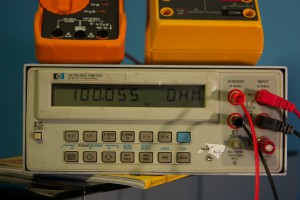
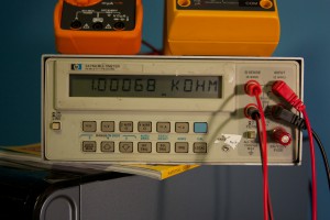
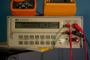
You will note that I used the 4-wire measurement function of this meter to measure these resistors. This allows the meter to remove any resistance from the test leads themselves (which ended up about a 2.5% error). Also, you may have noticed the “non-standard” test probe connector for the current measurement on the bottom right of the meter face: this was due to a the fuse holder/connector piece being missing (something I hadn’t noticed in the pictures of the meter on Ebay). I looked around, but even these HP meters being sold “for parts” were 100$+ and Agilent does not stock this part any more. I hacked on a binding post with a 3A fuse behind it and that solved that! So beware: when looking for this meter on Ebay or any other second-hand site, MAKE SURE you get the current socket + fuse holder!


Fluke 27/AN

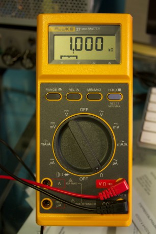
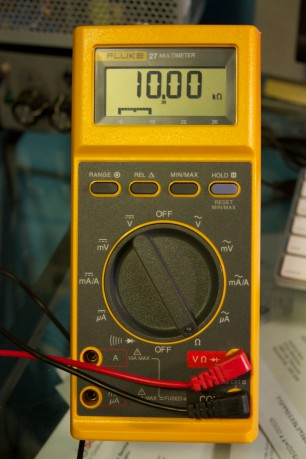
The last meter that I picked up on Ebay is a Fluke 27/AN for ~70$ + shipping, although it can be found cheaper: I have seen them for as low as 50$ for this version.  It is the “worst” of the three: a 3200 count instrument, +/- 0.1% + 1 count basic DC volts accuracy. So it is more accurate than my Agilent (in theory) but has less resolution than the Agilent. The reason I bought this meter was to have a nice solid, built like a tank meter that I would be confident enough to use with mains testing (if need be) and would be rugged enough to use outside the “lab” environment. It also has a 10A current range, which is handy (since the HP can only handle a maximum of 3A). With a rated 900 hour battery life, this meter is the one that I would trust to be working when I need it. Below are some shots of the same resistor measurements as above:

IMG_5299 IMG_5297 IMG_5298


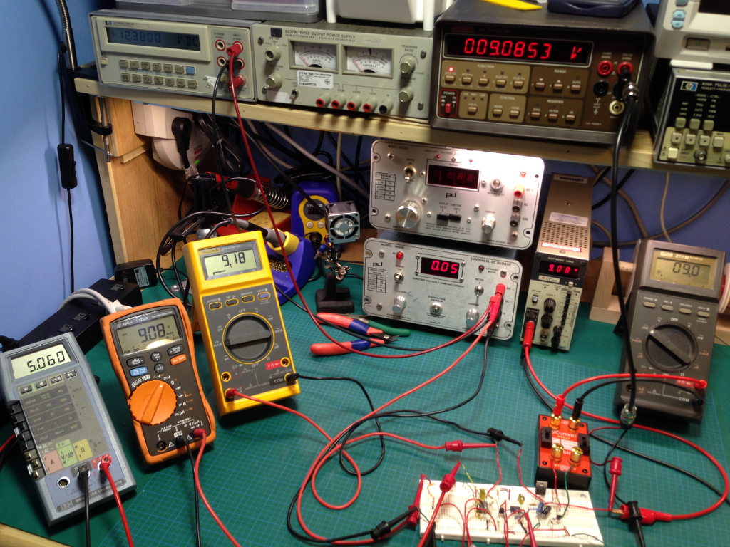
As a final test, here is a shot of all three meters connected to the same power source (DC voltage). As you can see, they are all almost exactly the same (of course the HP will have the most resolution, so we can ignore the least significant digits):

IMG_5285

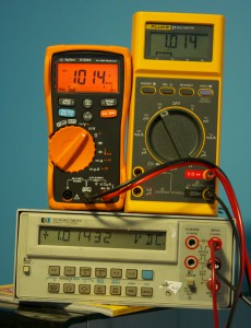
All in all, for a couple of second-hand meters, I am very pleased with the overall accuracy (assuming that the Agilent I have is reasonably well calibrated, since I am using it as a transfer standard). I do not have a meter that can measure temperature, so that might be the next thing to look for!