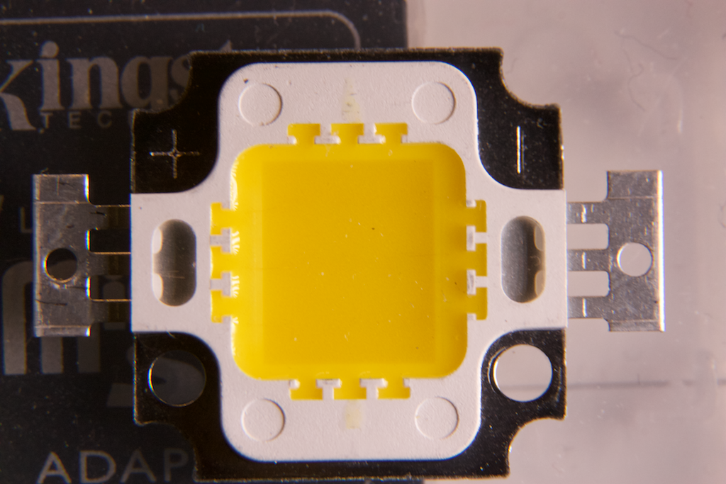
Several months ago I bought a set of 10W LED modules like this:
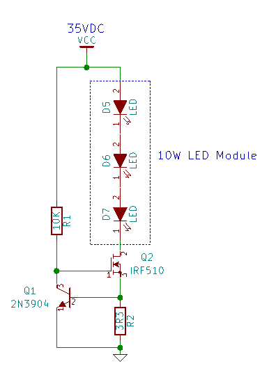
They have a multi-chip configuration, with an array of LEDs embedded in the center phosphor part. These units come in various voltages; the ones I got were ~30V. I designed a quick constant current circuit that runs off of a ~35VDC supply (open circuit, ~30VDC under load):
The constant current circuit is a simple N-channel MosFET with sense resistor feedback (using the 2N3904 to control the ‘FET). Knowing that there will be an ~0.6V drop between the NPN transistor’s base and emitter, we can calculate V=IR, or V/R = I, which gives us 0.6/3.3 = ~0.181A or 180mA through the LED module.
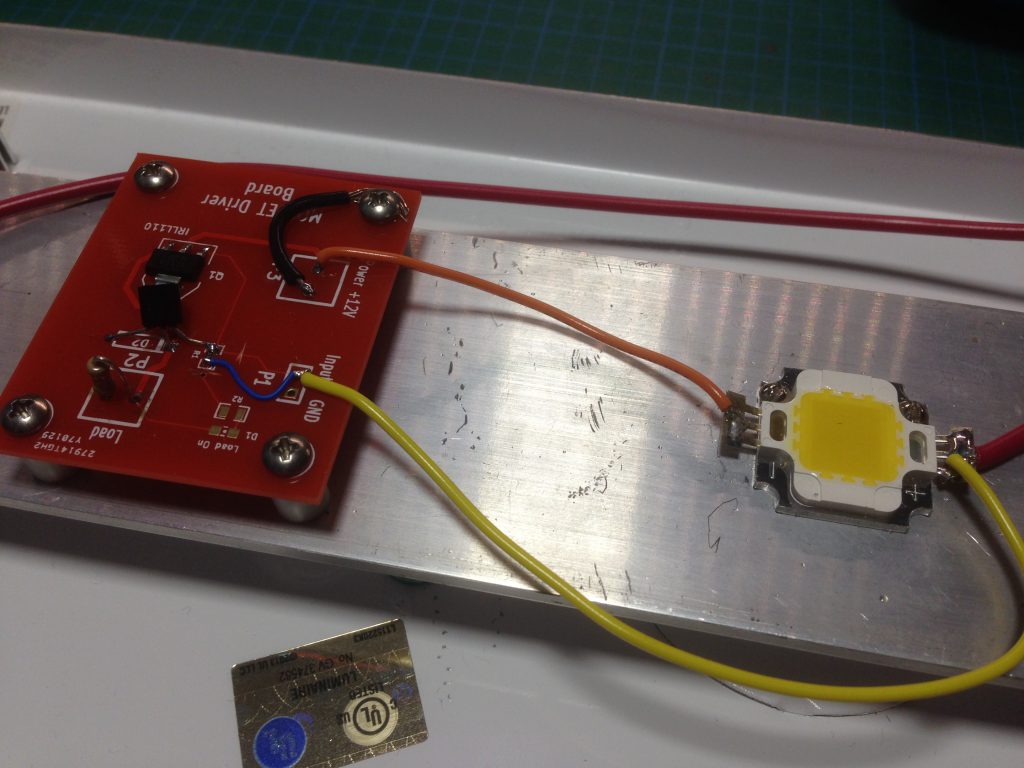
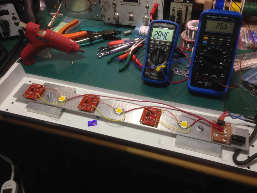
Here is a photo of the built circuit (there are 3 of them, one per LED module):
The PCB that I used was actually the first PCB that I ever designed, and it had an error so i never ended up using it. I modified the circuit on the PCB to accommodate the LED driver circuit above (reuse and recycle!).
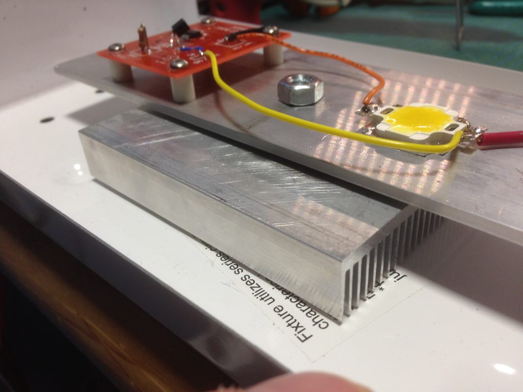
And from a different angle, showing the aluminum bar with the heat sinks under:
Originally I thought that it would be possible to thermal-paste and screw the main aluminum bar to the enclosure, but that didn’t work out too well in terms of height and clearances, so I added two big heat sinks (no idea what the specs are, they are “cheapie” ones from EBay). They do a good enough job, and the whole thing stays at a reasonable temperature as long as it is not left on for more than a few hours. Of note is that the heat sinks don’t make full contact with the aluminium bar; this will be fixed in the future, and I will be added a fan to the enclosure with some venting.
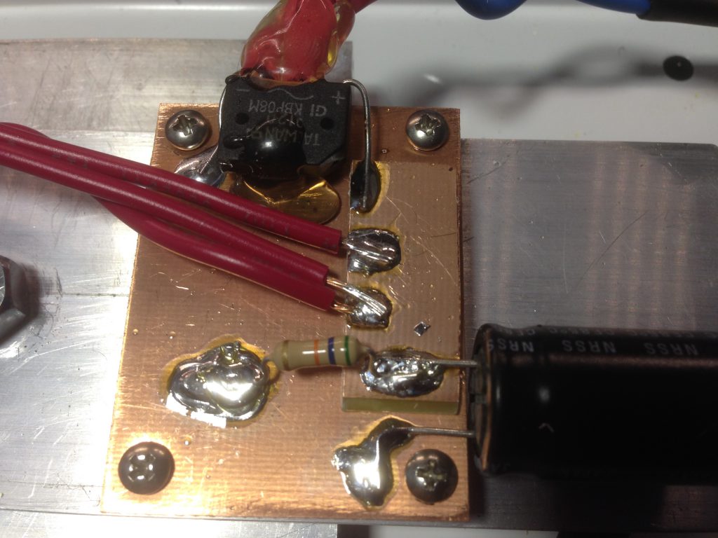
Here is a photo of the power input rectification and filtering board I put together:
Note the 56 kΩ resistor soldered to the filtering capacitor in the foreground. I ran into a small problem that there was enough residual voltage across the capacitor after the lamp was turned off that caused some of the LEDs with lower forward voltage drops to stay lit. The resistor helps drain the capacitor quickly.
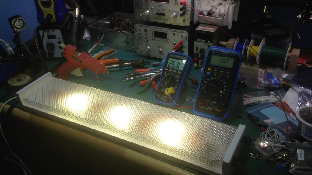
Here you can see the fully assembled unit on the electronics bench, plus a shot of it lit up during thermal testing:
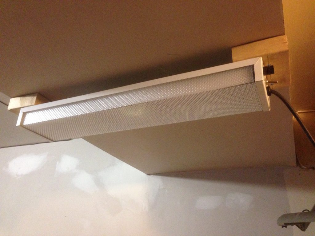
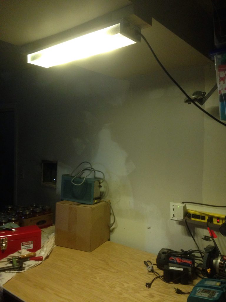
And here is the final light mounted above my work bench in the garage:
You can see in the back to the right the power bar with the AC adapter (right side of the power bar) that I used to power the light. It is a 24VAC unit (~27VAC without a load).
Measurements of the light output and power consumption will be performed and reported on in another post.

