I’ve been rather silent for a couple of months now, but I have been busy! This time it is a laboratory frequency standard! This project is modeled on the work done by Gerry Sweeney over on his blog. I have been assembling the various pieces needed for this build for several months now, and just recently decided to take the plunge and do the build.
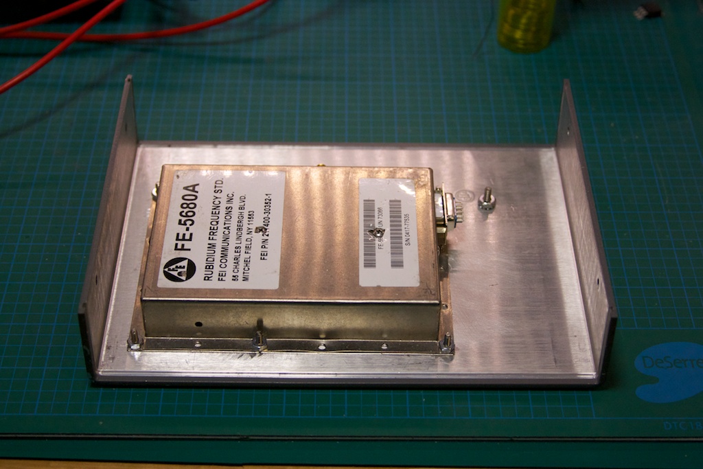
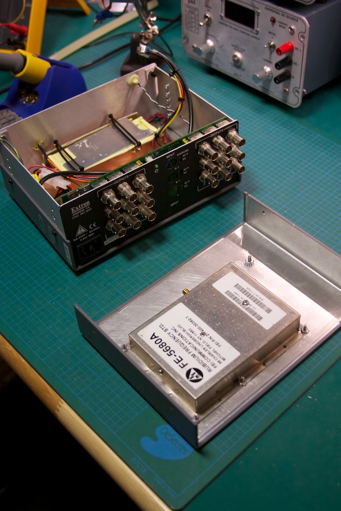
It started off with a Rubidium frequency standard from Frequency Electronics, the FE-5680A. These can be purchased used off of EBay for ~120$ CAD. Buyers beware: I had success with my first unit, but others have not been so lucky. There are numerous configurations of this unit, with various features present or missing, including the 10MHz sine output. This project requires at a minimum the 10MHz out. Some units will have this via a dedicated BNC or SMA connector, others (like my unit) will have it present on a pin from a DB-9 connector.
The second most important component is the case which will house the completed project. I was originally going to choose a basic project box, but Gerry was pointed towards a distribution amplifier for video. Since the signal from the FE-5680 would need to be replicated on multiple outputs to be useful, some sort of amplifier was going to be needed. It just so happens that 10MHz lies in the range of off the shelf video amplifiers, and the model I got by Extron, the ADA 6 Component was perfect for the job AND was only 40$ on EBay.
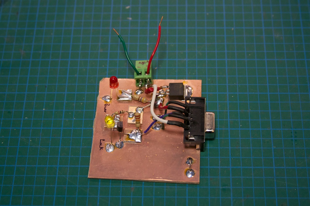
Other than just putting the Rb standard in a box with a bunch of outputs, I wanted to have an indicator LED that lit up when the Rb was locked on 10MHz. My particular unit will pull a pin on the DB-9 connector LOW when the Rb is locked. A quick transistor circuit with a regulator feeding off a 17V supply and I had a small prototype board completed:
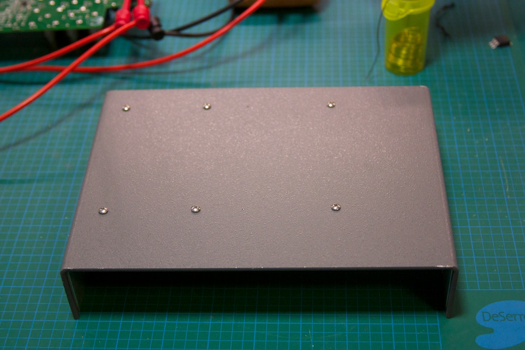
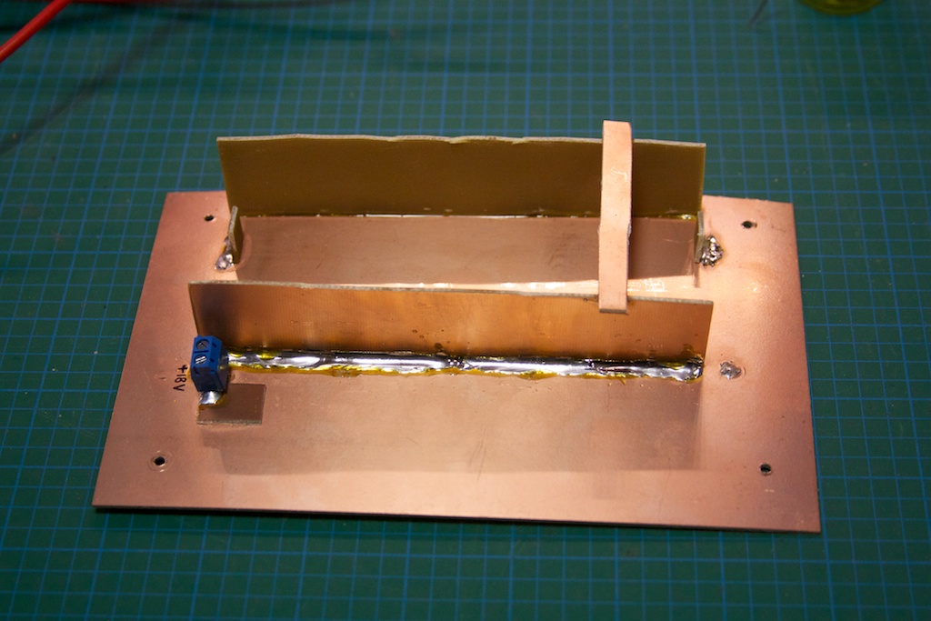
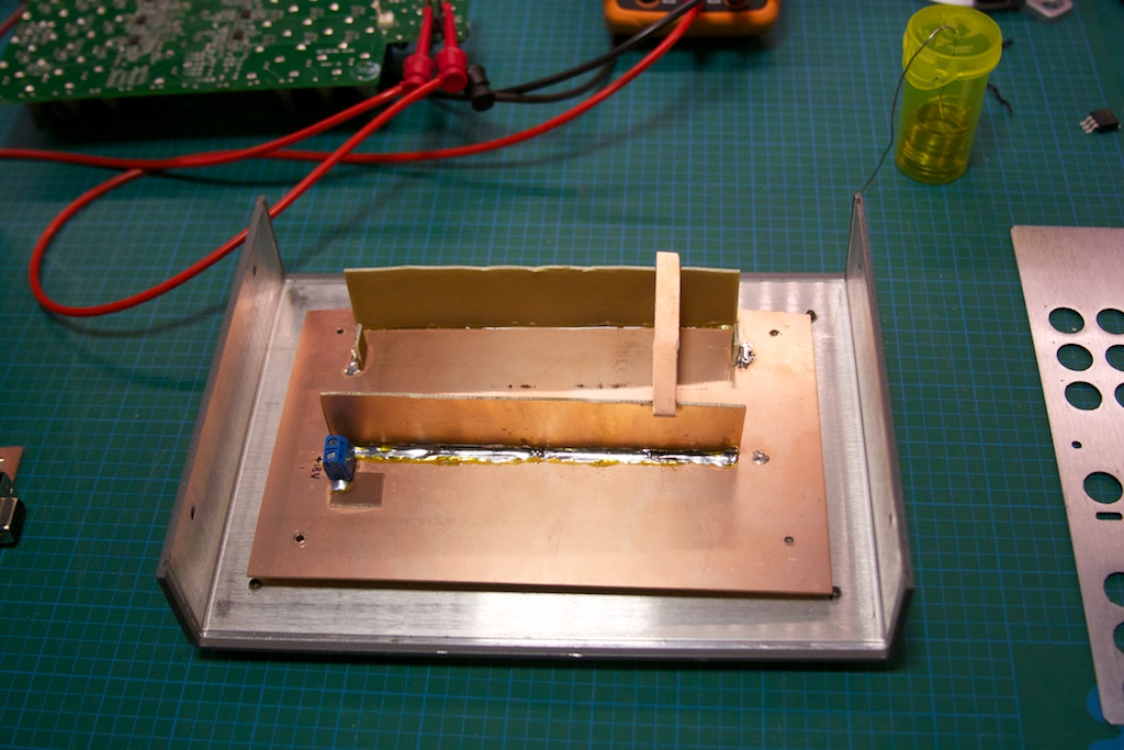
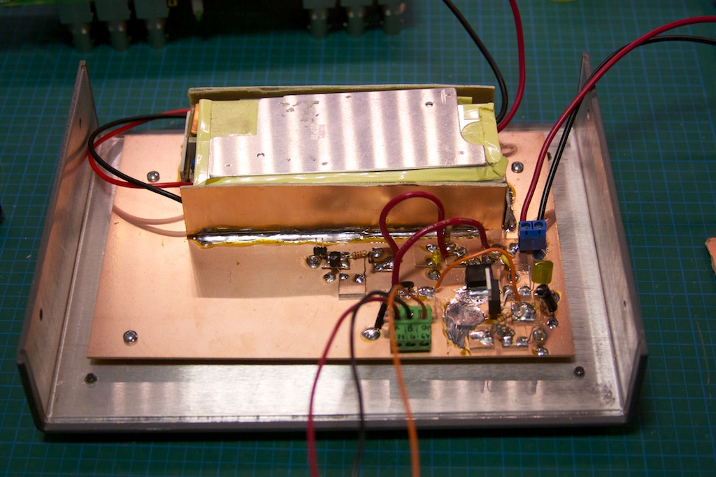
Once I had the “interface circuit” figured out, I started laying out what the mechanical construction of the project would look like. I decided to use the case itself as a heat-sink and seeing as how the Rb standard likes to be warm (haha, non-heat-sinked, the case measures ~65C), I decided to mount it to the top half of the box:
The Rb standard requires 2 different power inputs: 5V and15-18V. The distribution amplifier also required 2 different power rails: 6.2V and 17V. I decided that the easiest way to power it all would be to pick up a 18.4V laptop power brick, rip the guts out, and add a LM317-based regulator to get the 6.2V to my existing interface circuit. I discovered that the Extron was actually using the 17V rail to power a buck converter-inverter circuit, so the 18.4V input didn’t change it too much.
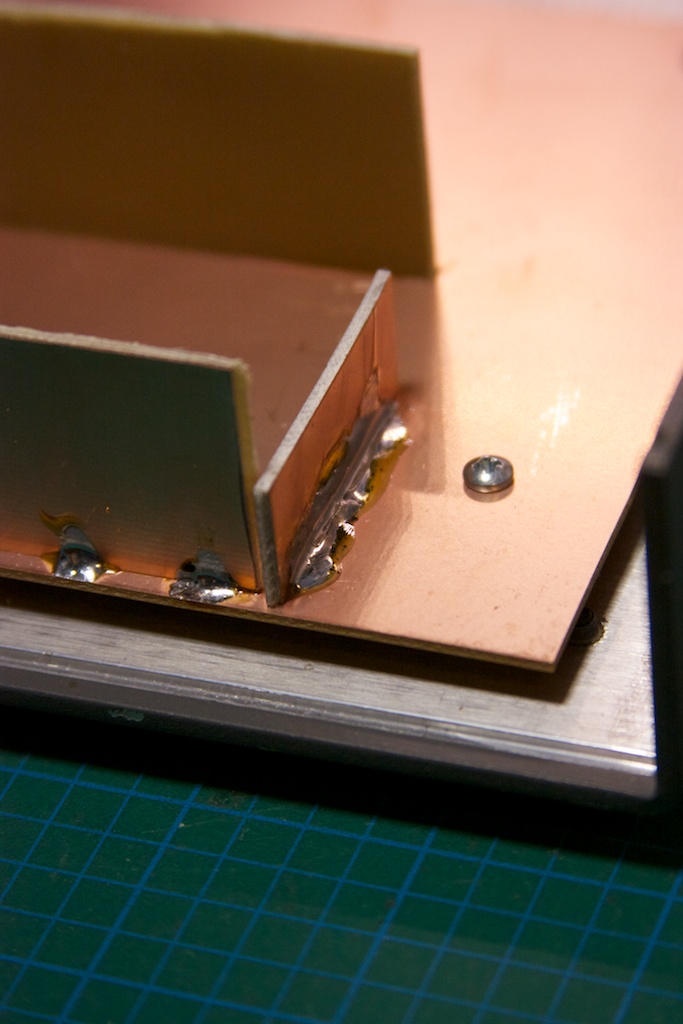
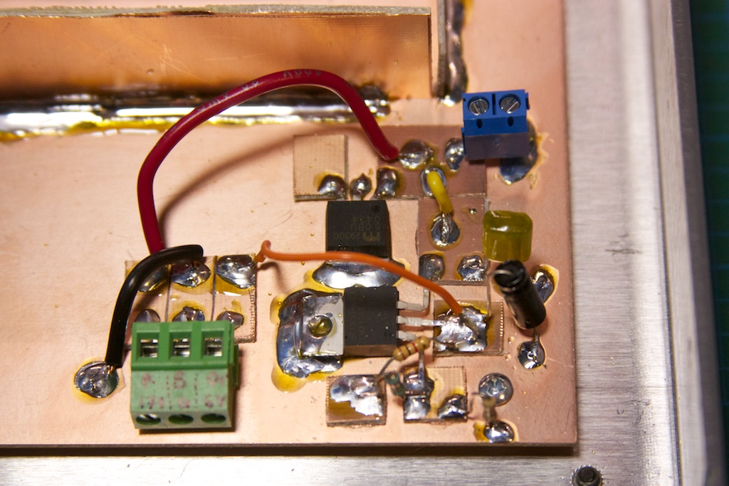
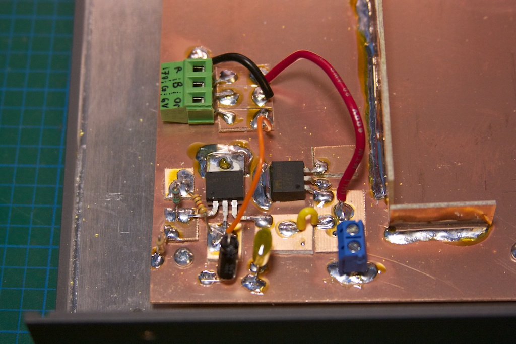
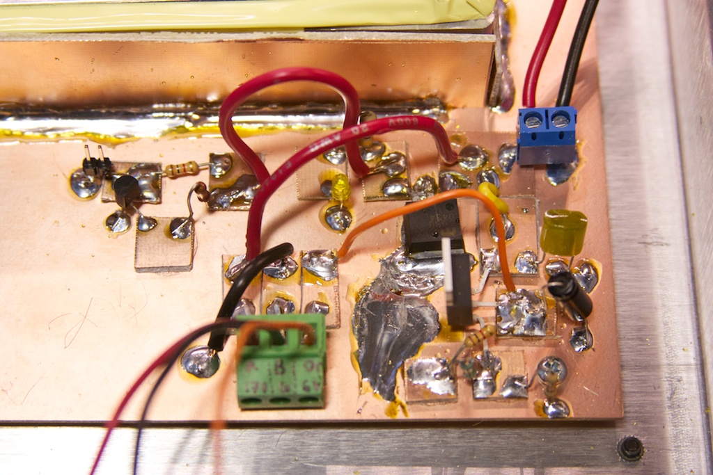
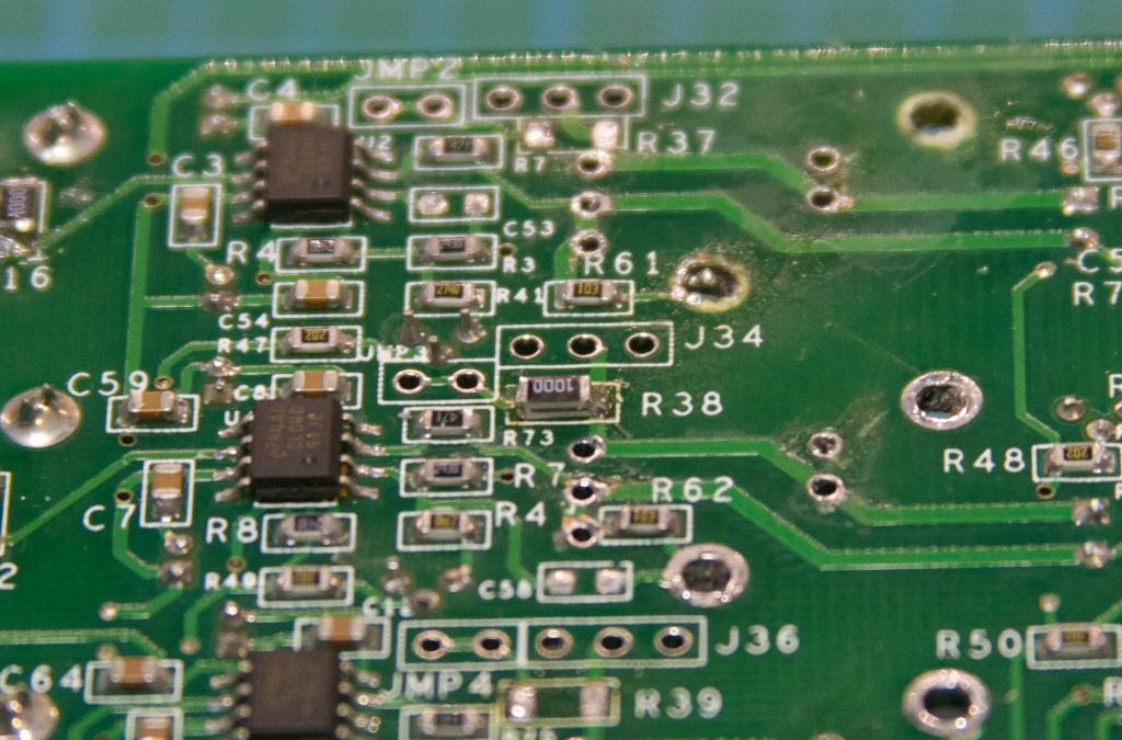
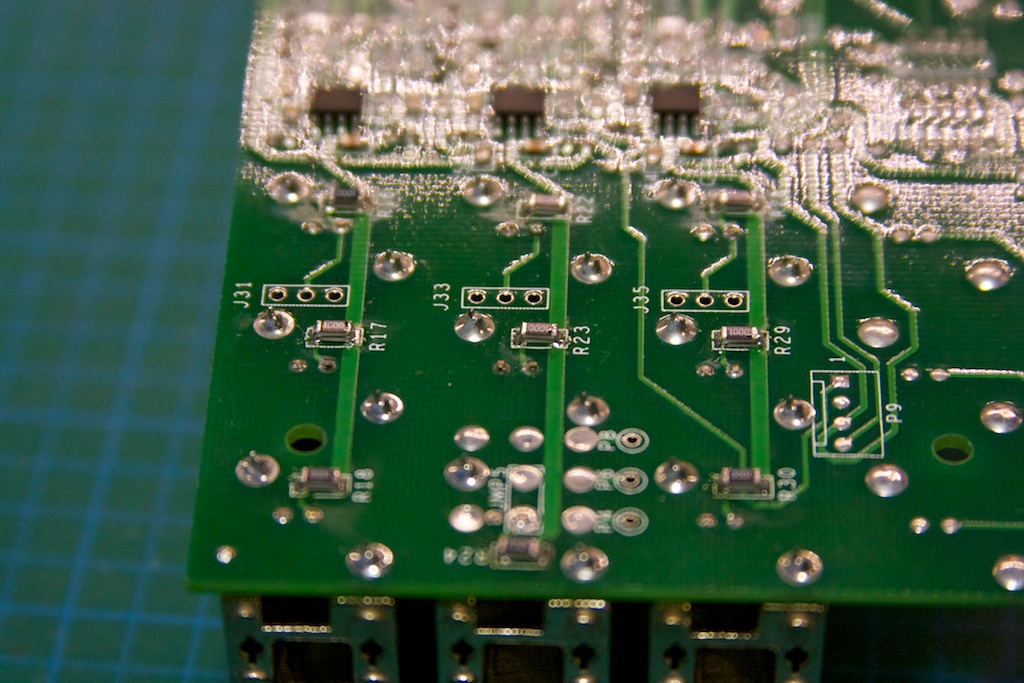
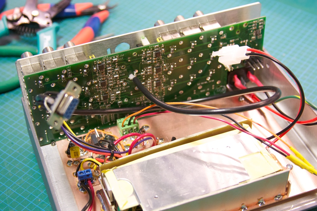
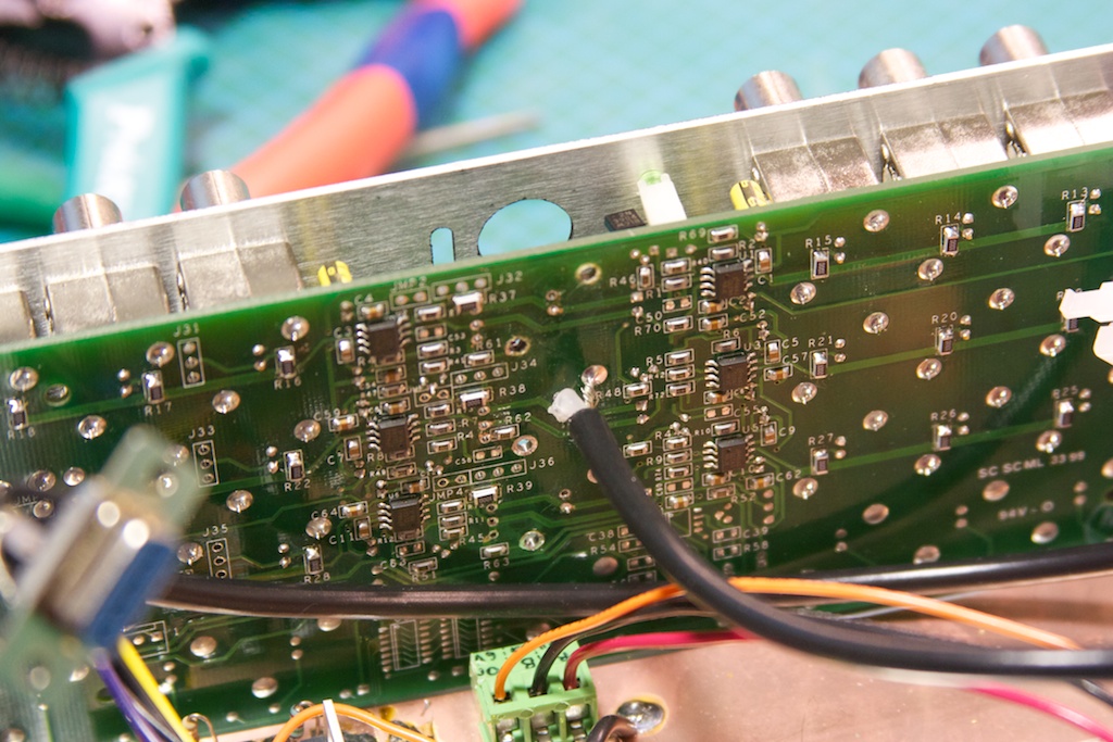
I wired up a small wiring harness to go from the Rb standard’s DB-9 connector to the various parts of the interface board. I then modified the amplifier board to change the input/output impedance from 75ohm to 50ohm:
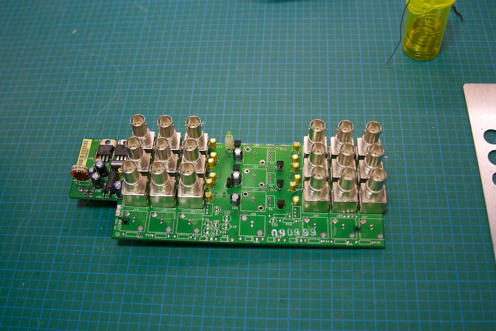
Not having any 50ohm resistors handy (and they’re damn expensive as well!), I used 2 100ohm resistors in parallel stacked on top of each other:
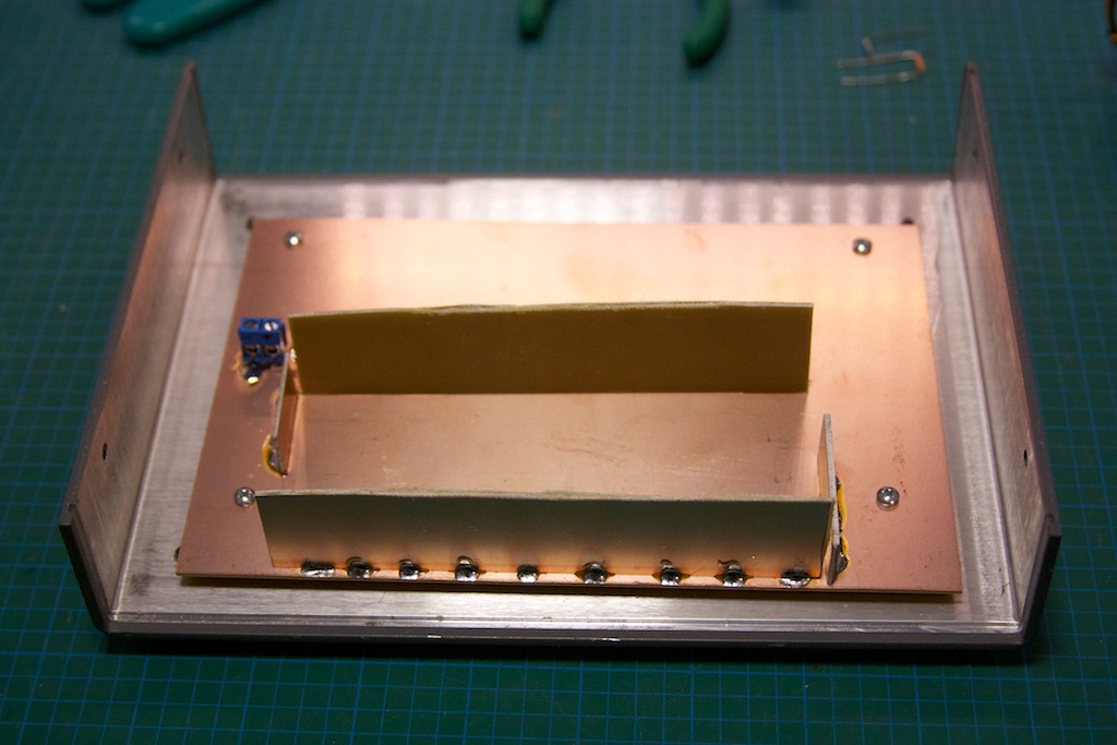
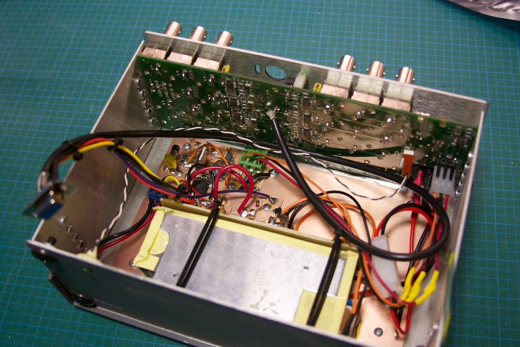
I soldered in the coax to the center channel, and then jumped the signal from the center channel to the 2 other ones with some wire. This means I will have a total of 18 10MHz outputs on this standard 🙂
The testing and assembly: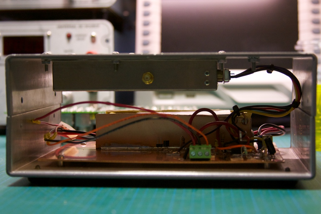
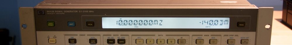
I ran into one problem when testing, which was a deformed lower part of the sine wave on the outputs (all of them). You can see it on the oscilloscope to the upper right:
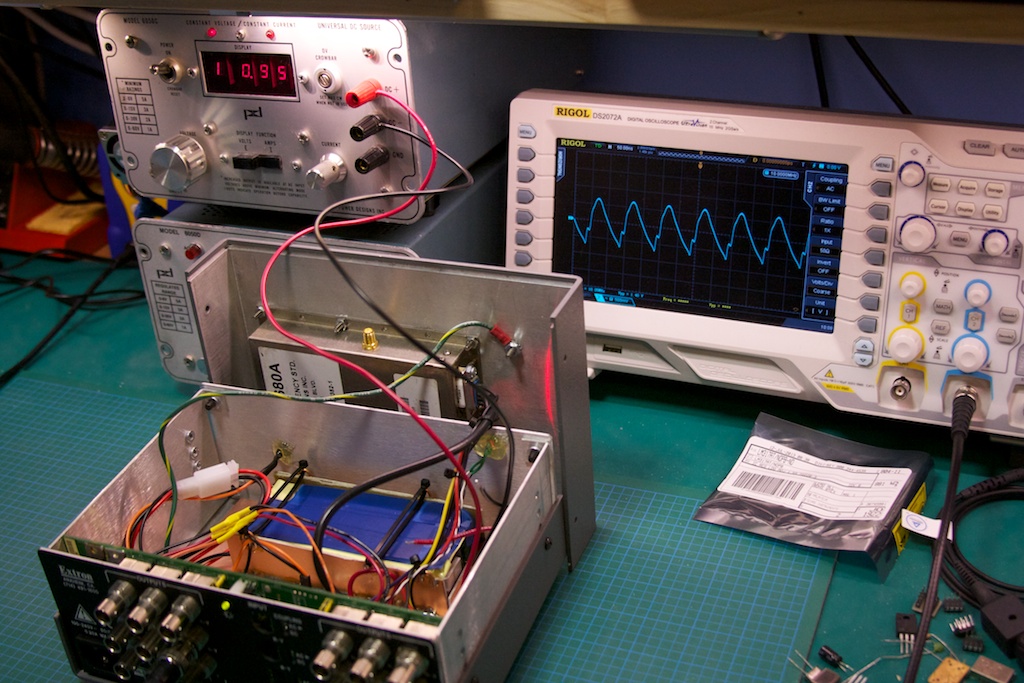
I started probing around (“THOU SHALL CHECK VOLTAGES!”), and discovered that the negative rail to the op-amps was running at ~0.3V, which was not right. Running back through the circuit on the amplifier board I realized that I had flipped the 6.2V and 17V rails on the input connector after splicing it into my interface board. After switching them back, everything was working as expected!
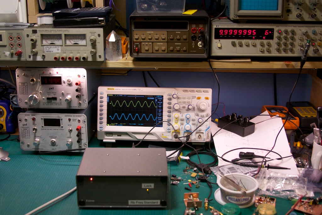
Turns out my frequency counter on the upper right is probably off by 0.5 Hz… not too shabby. There are a couple of things that need to be done: adding a heat-sink to the top of the case for extra dissipation and adding some passive ventilation holes on the top/back of the case and on the bottom.
Thanks for the write up! I’m in the middle of going through this myself. Looking at your photos, it appears that for the 3 input channel resistors (not the 18 output resistors), you replaced all 3 of the 75 Ohm resistors with 50 Ohms (2x 100Ohms in parallel) each. If you take the 3 channel inputs (RGB) and connect the inputs in parallel, you only need one 50 Ohm termination, not 3. If you connect the 3 channels in parallel, the 3 termination resistors on the input channels actually become connected in parallel so the termination resistance applied by the video distribution amp becomes 16.67 Ohms. If you want 50 Ohm termination on the amp side, you’ll need to take out 2 of the 3 resistors: R37, R38 or R39. On mine (I have the same video disp amp as you do, the 6 output channel, not the 8 like Gerry used) I just left in the R37 and removed R38 and R39. No other change is required and you can confirm with an ohm meter that you have 50 Ohms across the input on the amp. If you measure yours right now between the core and shield of the input coax, it should read 16.67 Ohms. It’s a fun project, thanks for the write up and photos!
Funny enough, after checking my mods, it turns out I have exactly the mod you describe, so I must have realized this and changed the circuit modification and not updated this post 🙂 I will do so!
Interesting, I will have a look at that tonight. I noticed that the signal out of the amp seemed a little funny but I hadn’t had the time to look over it closely. I will do so tonight! Thanks for the feedback!
How do you set the impedence. Swap the resistor for signal to groud resistor at 50 or 75 ohms?
Yep, that is exactly the mod you need to do. As Patrick above mentioned, if you are going to feed all of the inputs on this amplifier with the 10MHz signal, you only need to swap the impedence resistors on a single input. I choose the middle channel and because 50ohm resistors seem to be difficult to source, I stacked 2 100ohm resistors in parallel.
The FE5680A a 50 ohm unit, so there is a mismatch at the distribution board?
In that, wouldnt you be adjusting for the difference of 25 ohms instead of resetting the impendence to 50 ohms as required?
The impedence is set by the resistors connected to ground alone, would it require a transfomer in the circuit to adjust, i.e matching pad from 75 ohm to 50 ohm with a few db loss in signal?
Of this I am not sure. There is an amplifier in between the input/outputs which should isolate the two impedances. That being said, I modified the impedance to 50ohm (in the same way) on all the outputs as well so it should be matched right through. The impedance (from the little I know) applies primarily to the transmission line (input and output) so it should not impact the amplifier internals.
Cool, so the impedence is adjusted by a resistor from 10m signal to ground?
Where is the amp board from, is it for audio/video use as impedence is set for 75 ohm normally. Is it adjustable for output gain v/rms also?
Oh, i see, Extron distribution amp.
Yup! You can find the model I used or Gerry used on Ebay, and usually for not too much. There is not much to modify, but then again, there’s not much to the circuit to begin with. It is mostly a lazy thing, as a video distribution amp will typically have all the hardware and case already done for you. If you have a look, Dave Jones from the EEVBlog got his hands on a Rb Standard from a government cal lab and it was essentially a rackmount video amp + a Rb Standard grafted into it. So you can probably just hunt around for an older video amp and you’ll be set.
2 Thumbs up ! for a great idea mount the rb in the distribution amp chassis.
It was Gerry’s video (linked at the beginning of my post) that put me onto the idea, so kudos to him 🙂 But thank you!
Did the waveforms improve with impendence matching. It is said that below frequencies of 10mz, impendence dont really matter of mismatched 75 and 50ohm unless in very long cables.
I suspect you’re right. As far as my knowledge goes, I suspect it will only affect the signal magnitude at 10MHz.