Avoiding Panic

This is a re-post of a comment that I made on my Facebook profile a couple of months ago regarding the temporary dumping of raw sewage into the local river by a city near where I live. There was a fair amount of buzz around this issue, which in the end, I can understand the need to discuss, but was seemingly blown out of proportion.

I’d like to preface this with saying I am totally, 100% against the dumping of raw sewage into our rivers and lakes as a policy. And 8 billion liters sounds like an awful lot of raw crap to be dumping in our river. The St. Lawrence flows at a rate of approx. 16800 cubic meters per second. This is the amount of water if you picked a point along the river and measured the volume of water that passed across that point in 1 second. And that’s every second (and it obviously changes with seasons). So how long will it take to “flush” the 8 billion liters of crap the City of Montreal wants to dump in the river? Well, there are 1000 L in 1 cubic meter, so 8 billion liters can be converted to 8 million cubic meters (still horrifying!). To find out how long it takes the St. Lawrence to move 8 million liters, we divide 8 million by 16800, which gives us… 476 seconds. That’s about 8 minutes. I believe the City wants to dump this sewage over a 1 week period, so if we assume they do it evenly (which of course is a guess, I’m sure it will vary), that means 8 million cubic meters divided by 7 days, giving about 1.2 million cubic meters per day. Divide that by 24, you get 50000 cubic meters per hour. Divide that by 60, you get 833 cubic meters per minute. Divide /that/ by 60, and you get about 14 cubic meters per second. That’s a lot of crap. But considering even if the 16800 cubic meters per second flow rate is off by 100 (so 168 cubic meters per second instead), the river will wash that crap towards the ocean in about 1/100th of a second after dumping it.  This is a travesty if it were done on a daily basis as a policy. But as a once in a while thing?  I’m not so sure it’s all that important to get terribly worked up over. I will leave it to you the reader to figure out where that sewage would normally go if it was extracted from the waste water when all the sewage handling systems are working. The answer might surprise you.


Function Generator Shenanigans

So my problem turned out to be not the saving of the status of the HDG2002, but actually doing the following:

  • Go to Utility, select System Status
  • Toggle the “Startup” option to “Last” (to set the function generator to restore to the last setup before power-off I assumed!)
  • Exit back to the main channels screen
  • Power Cycle the generator using the power button on the front panel.

When the HDG2002 reboots, POOF! No more main screen after the Hantek logo briefly flashes on screen. So what happened? It turns out that the problem is actually that the BACKLIGHT is set to level 0 by doing the above procedure. I found this out by logging into the serial console and finding the /dso/app directory. In here, there are a couple of “test” binaries:

test_beep
test_bkl

I tried them both but the test_bkl was the interesting one. When I ran it with the following options:

./test_bkl on 105

Poof the display popped back on! Of course on reboot it turned back off again. So after temporarily re-enabling the backlight, I went back into Utility -> System Status -> Startup and set it to Default, power cycled and boom, back in business no worries.

Well I guess there are still a few bugs in the firmware.  Please note that you can run into this bug REGARDLESS OF WHETHER YOU CRACK THIS FUNCTION GENERATOR OPEN OR NOT, and it has nothing to do with modifying the HDG2002. Except that if you don’t crack it open after you do this, you seemingly have no way to recover.

Hope this helps someone else!

Lab Frequency Standard

I’ve been rather silent for a couple of months now, but I have been busy! This time it is a laboratory frequency standard! This project is modeled on the work done by Gerry Sweeney over on his blog. I have been assembling the various pieces needed for this build for several months now, and just recently decided to take the plunge and do the build.
It started off with a Rubidium frequency standard from Frequency Electronics, the FE-5680A. These can be purchased used off of EBay for ~120$ CAD. Buyers beware: I had success with my first unit, but others have not been so lucky. There are numerous configurations of this unit, with various features present or missing, including the 10MHz sine output. This project requires at a minimum the 10MHz out. Some units will have this via a dedicated BNC or SMA connector, others (like my unit) will have it present on a pin from a DB-9 connector.
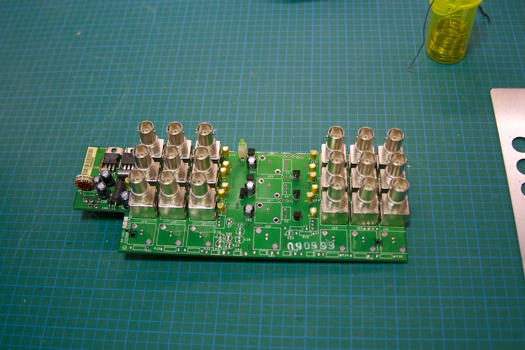
The second most important component is the case which will house the completed project. I was originally going to choose a basic project box, but Gerry was pointed towards a distribution amplifier for video. Since the signal from the FE-5680 would need to be replicated on multiple outputs to be useful, some sort of amplifier was going to be needed. It just so happens that 10MHz lies in the range of off the shelf video amplifiers, and the model I got by Extron, the ADA 6 Component was perfect for the job AND was only 40$ on EBay.

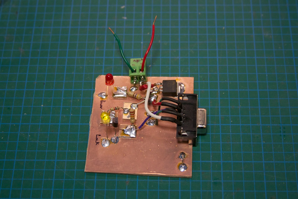
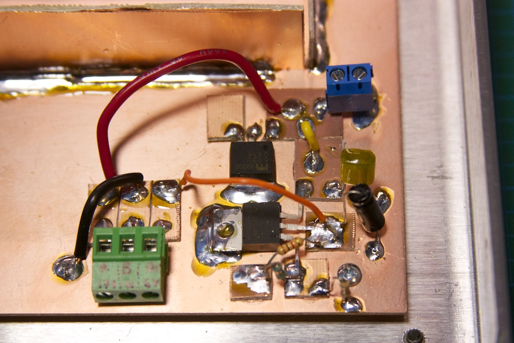
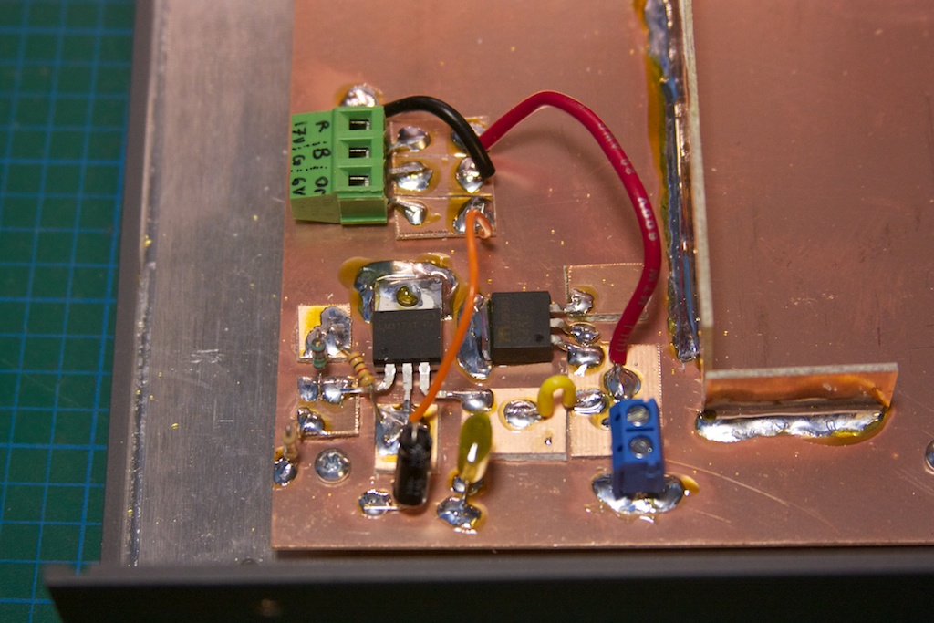
Other than just putting the Rb standard in a box with a bunch of outputs, I wanted to have an indicator LED that lit up when the Rb was locked on 10MHz. My particular unit will pull a pin on the DB-9 connector LOW when the Rb is locked. A quick transistor circuit with a regulator feeding off a 17V supply and I had a small prototype board completed:

IMG_5579

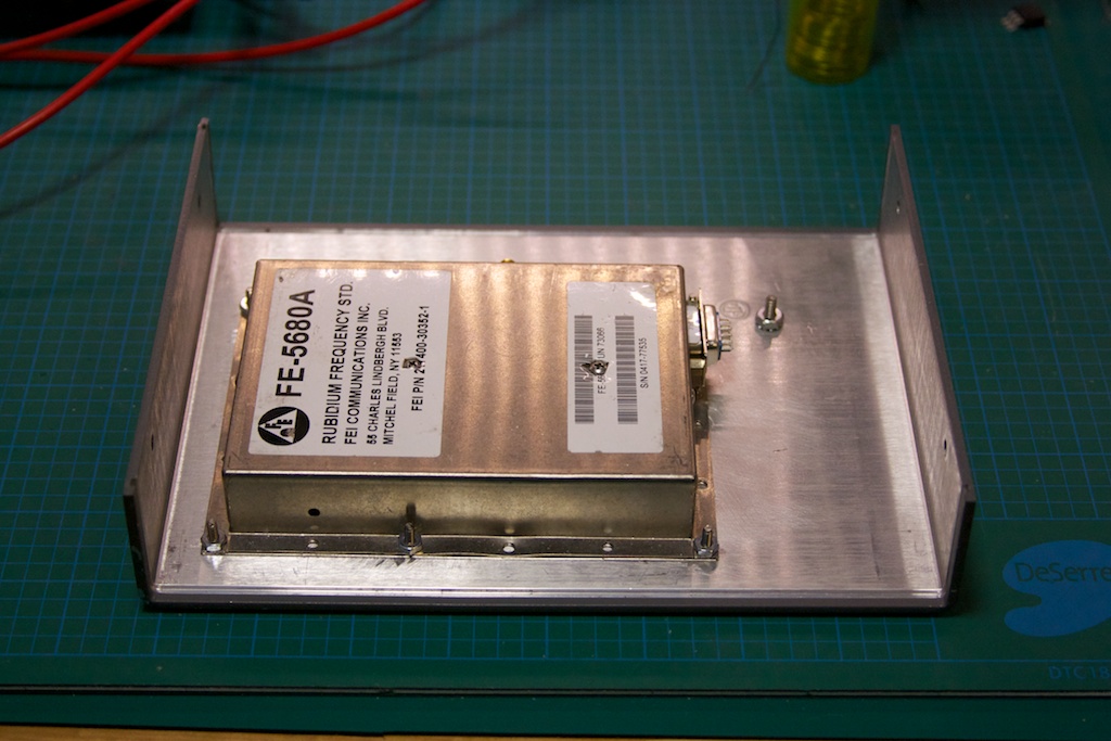
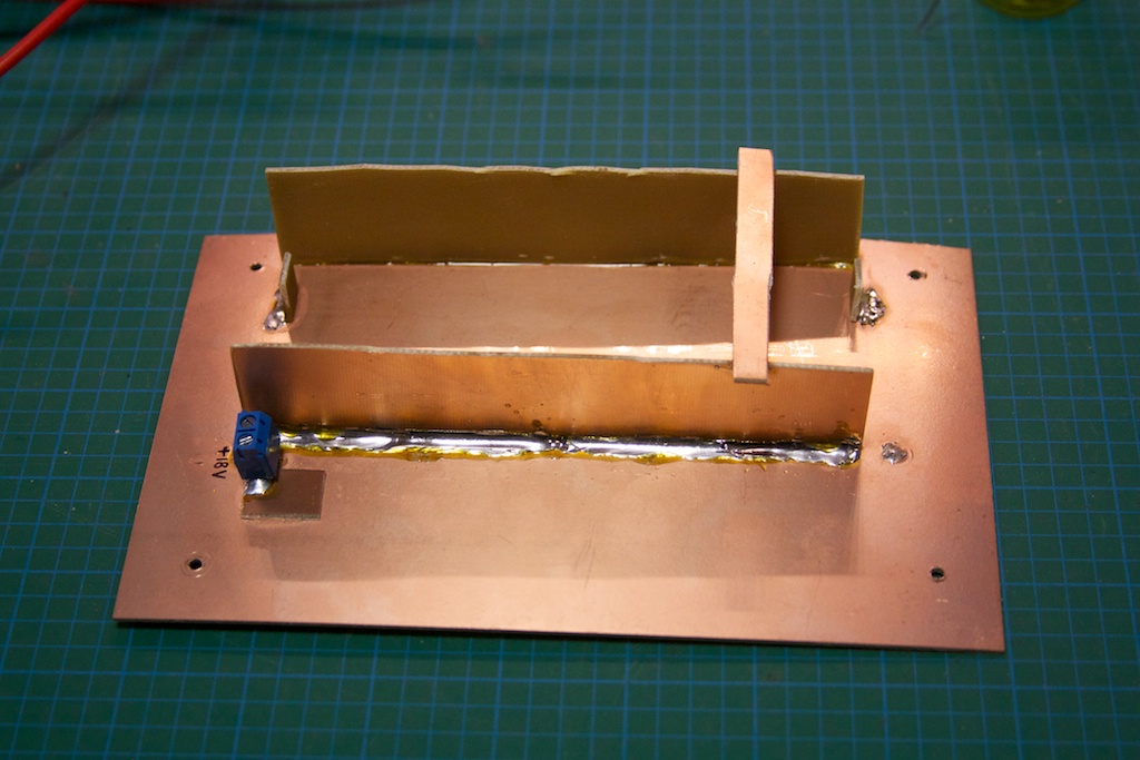
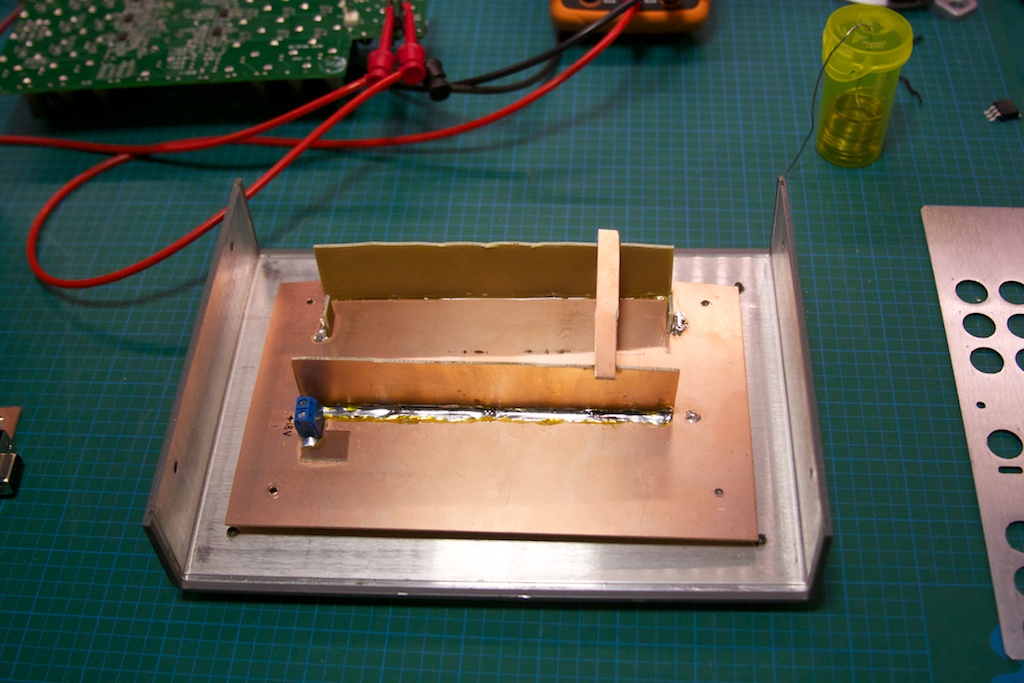
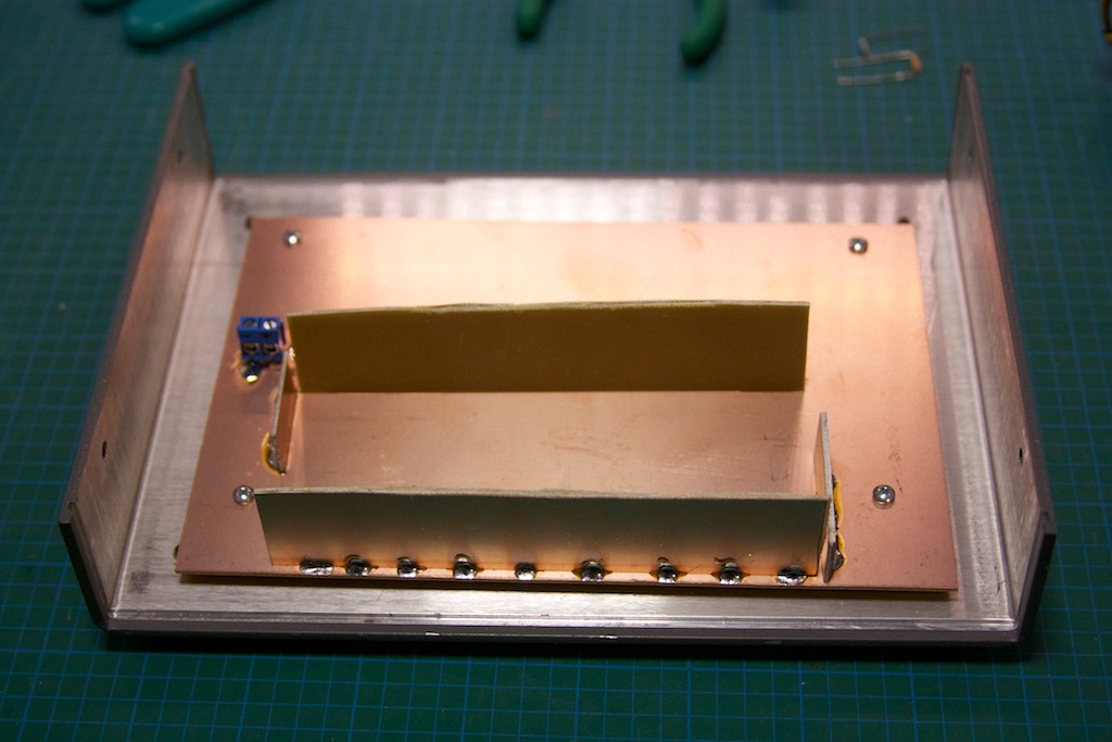
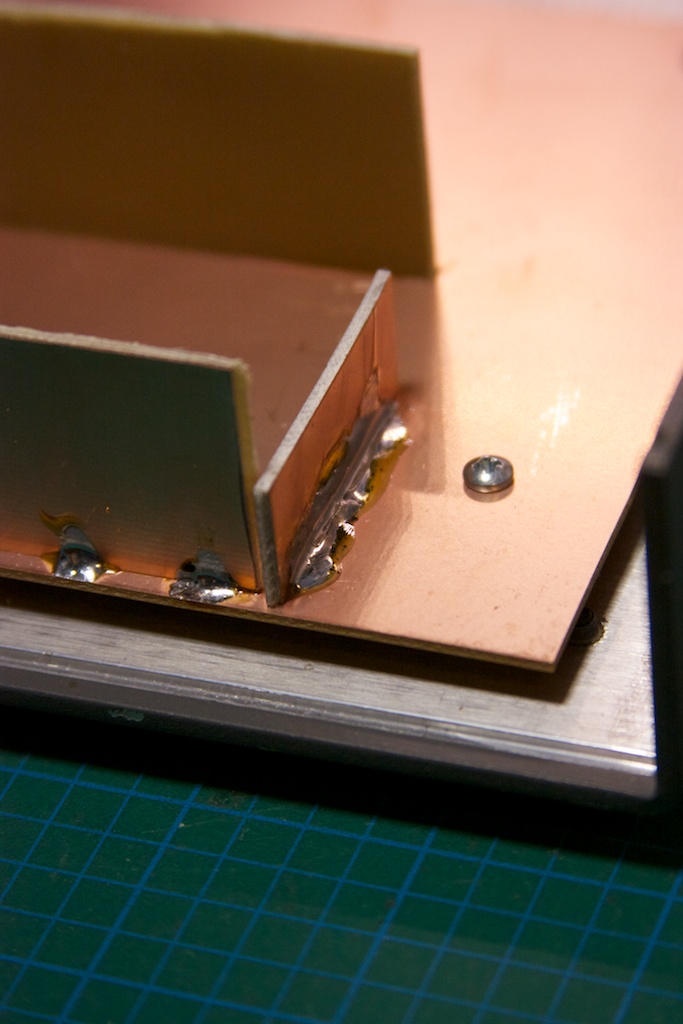
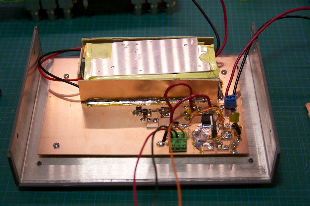
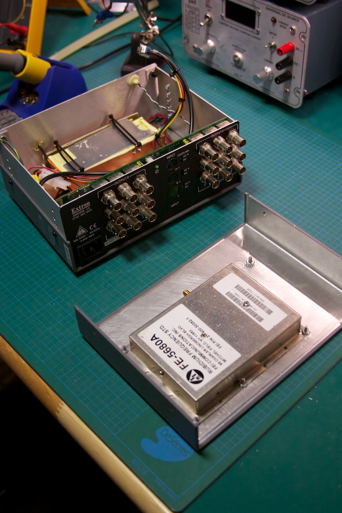
Once I had the “interface circuit” figured out, I started laying out what the mechanical construction of the project would look like. I decided to use the case itself as a heat-sink and seeing as how the Rb standard likes to be warm (haha, non-heat-sinked, the case measures ~65C), I decided to mount it to the top half of the box:

IMG_5577 IMG_5578

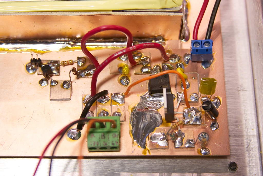
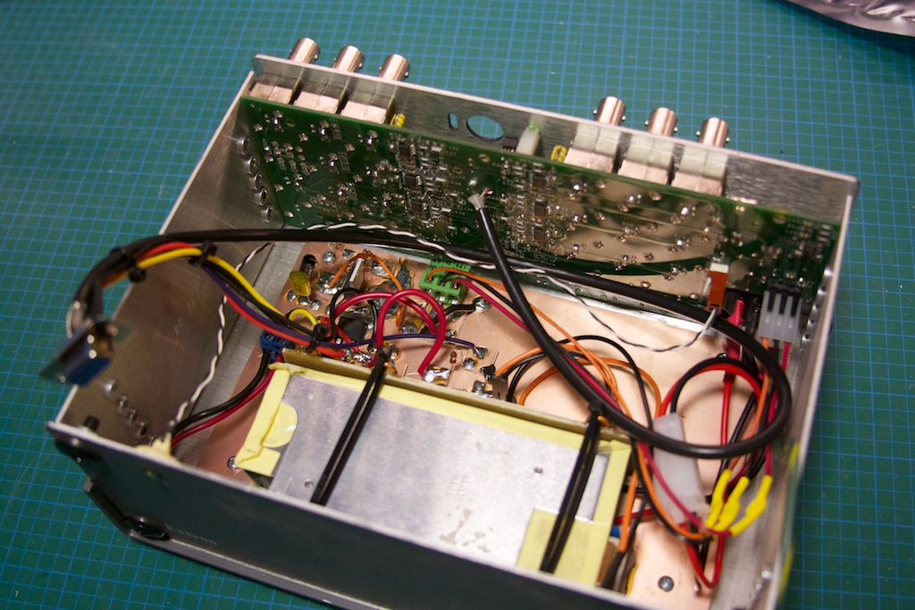
The Rb standard requires 2 different power inputs: 5V and15-18V. The distribution amplifier also required 2 different power rails: 6.2V and 17V. I decided that the easiest way to power it all would be to pick up a 18.4V laptop power brick, rip the guts out, and add a LM317-based regulator to get the 6.2V to my existing interface circuit. I discovered that the Extron was actually using the 17V rail to power a buck converter-inverter circuit, so the 18.4V input didn’t change it too much.

IMG_5580 IMG_5581 IMG_5585 IMG_5587 IMG_5588 IMG_5589 IMG_5590 IMG_5591

I wired up a small wiring harness to go from the Rb standard’s DB-9 connector to the various parts of the interface board. I then modified the amplifier board to change the input/output impedance from 75ohm to 50ohm:

IMG_5582

Not having any 50ohm resistors handy (and they’re damn expensive as well!), I used 2 100ohm resistors in parallel stacked on top of each other:

IMG_5584 IMG_5583

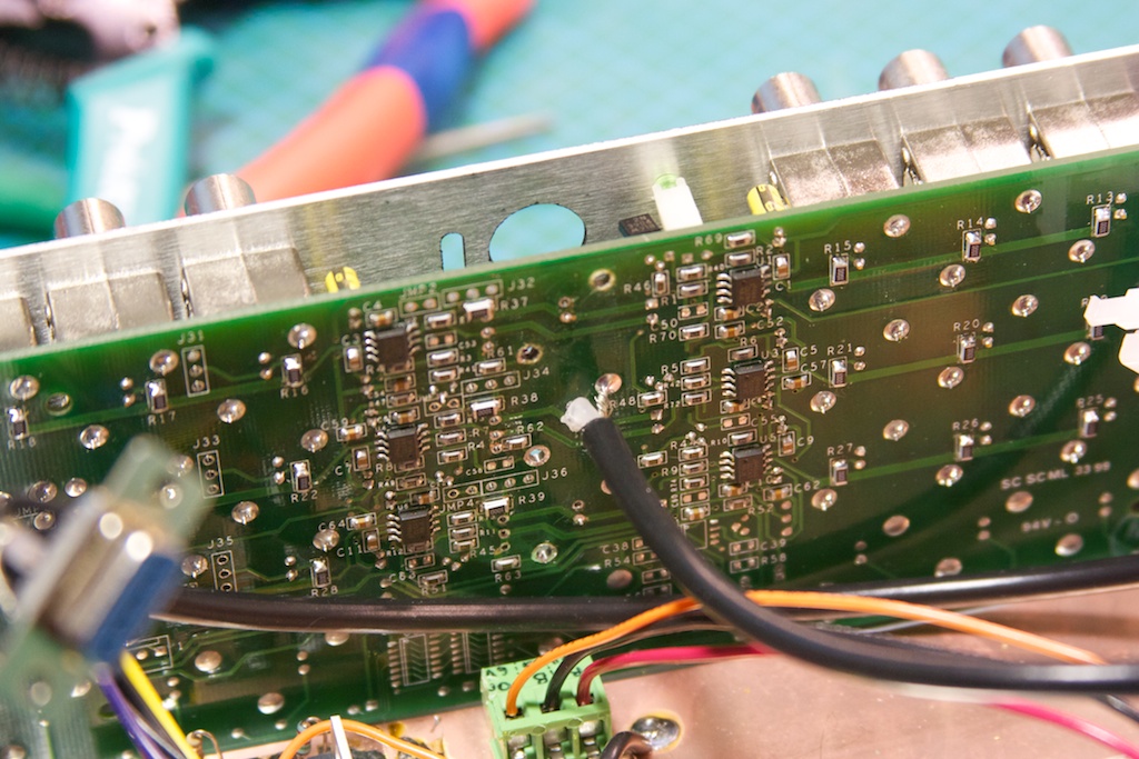
I soldered in the coax to the center channel, and then jumped the signal from the center channel to the 2 other ones with some wire. This means I will have a total of 18 10MHz outputs on this standard 🙂

The testing and assembly:IMG_5593 IMG_5597 IMG_5598 IMG_5600 IMG_5601

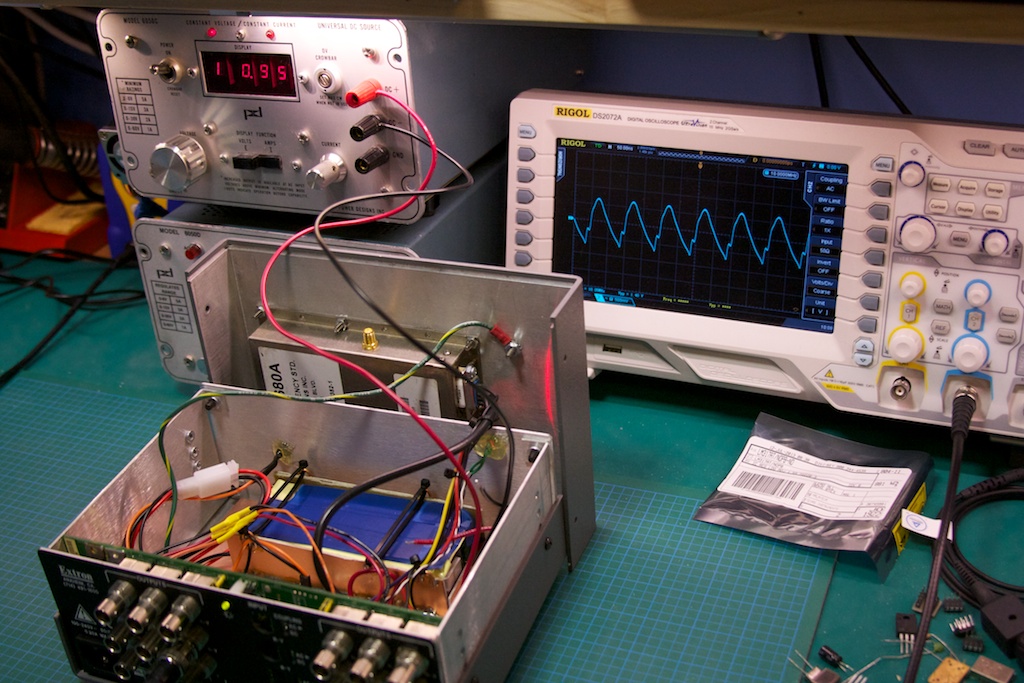
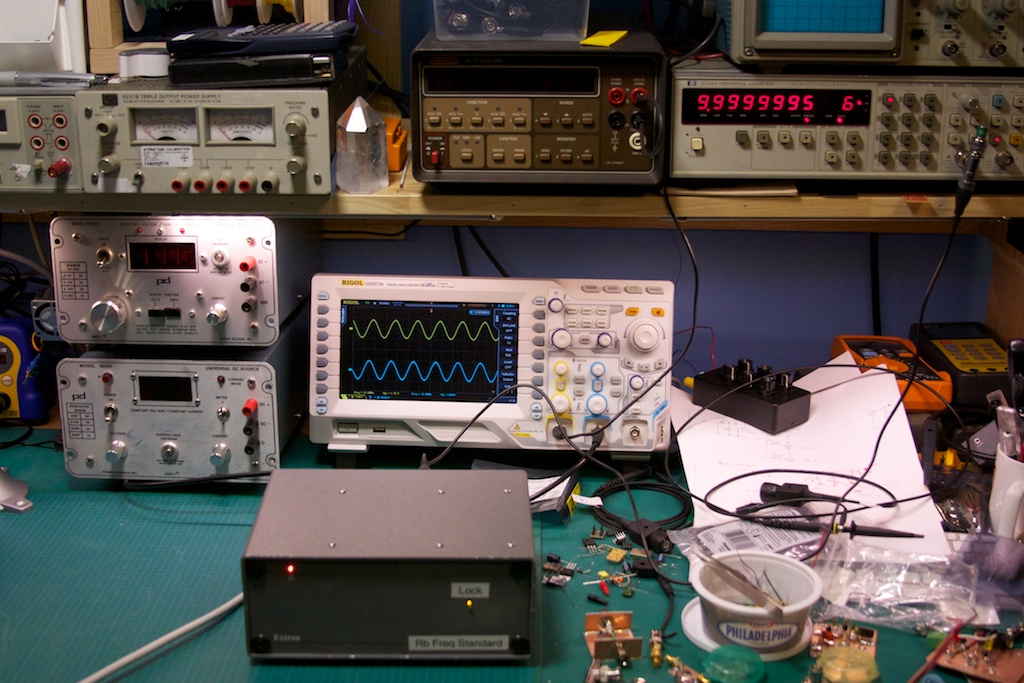
I ran into one problem when testing, which was a deformed lower part of the sine wave on the outputs (all of them). You can see it on the oscilloscope to the upper right:

IMG_5602

I started probing around (“THOU SHALL CHECK VOLTAGES!”), and discovered that the negative rail to the op-amps was running at ~0.3V, which was not right. Running back through the circuit on the amplifier board I realized that I had flipped the 6.2V and 17V rails on the input connector after splicing it into my interface board. After switching them back, everything was working as expected!

IMG_5604

Turns out my frequency counter on the upper right is probably off by 0.5 Hz… not too shabby. There are a couple of things that need to be done: adding a heat-sink to the top of the case for extra dissipation and adding some passive ventilation holes on the top/back of the case and on the bottom.

New Threat On The Block

I know many of us run Windows and perhaps have home networks, etc etc. I also figure that a few of you have at least one important document that may not be backed up. There is a “new” nasty virus out in the wild, called Cryptolocker.

What is it?

This virus seems to spread via email and is a Windows (for now) executable file that you have to run on your computer. Once this happens, this virus starts to encrypt all of your documents (a fairly complete list is in the link below) with a VERY secure key. It can also encrypt all document files of other users on the system if the account that it is running as is an Administrator user. It will also try to encrypt all files it finds on mapped network drives.

After this is finished (and you don’t get a helpful pop-up saying it’s doing this BTW) it will prompt you to pay a certain amount (I think it is 300$ USD or something) for the decryption key and it will start a timer count down. If you don’t pay up by the time the counter hits 0, it will remove itself and any possibility of recovering your files (it keeps the key that is required to decrypt your files on a random remote server).

How do I prevent being bitten by this thing?

Funny enough, the solution is rather simple: back-up your data to an offline location (external hard disk for example). Do not use a “cloud”-based online backup solution as they will typically over-write your good files with the encrypted versions. So avoid a disk imaging style back-up; this will just result in you backing up your encrypted files before you know you have the virus.

What do I do if I get it?

No, that anti-virus software isn’t all that useful (at least not yet) since many (if not all) AV software vendors have yet to update their software to protect against this virus. The only way to get your data back for the moment is to pay the ransom. If you DO get hit with this thing and you intend to pay the ransom:

  • DO NOT MOVE OR TOUCH ANY OF THE ENCRYPTED FILES; otherwise even with the key the virus will not be able to decrypt your files;
  • DO NOT install or update your anti-virus software; the current few that recognize this virus will simply remove it, along with the key that you would need to decrypt your files and any chance of you getting your data back.

If you would like more detailed (read: technical) information, please have a look at this thread:

http://www.reddit.com/r/sysadmin/comments/1mizfx/proper_care_feeding_of_your_cryptolocker/


Electronics gear, Part 1 – The Meters

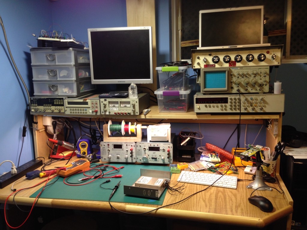
After spending both a bit of time and money, I have assembled a set of tools both new and used to help me on my path to learning a bit about electronics. This first post will be about the most basic of tools for any individual that is interested in electronics, the multimeter.

Agilent U1232A

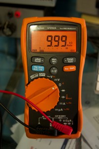
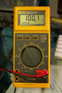
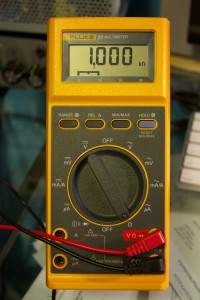
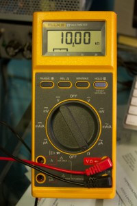
Originally I was going to buy 2 meters, one high quality one for my primary meter and a secondary one for measuring simultaneous current or an additional voltage. To this end I purchased an Agilent U1232A (6000 count, basic DC accuracy of 0.5% + 2 counts) to use as my primary calibrated meter. I bought it at Active Tech for 150$ + shipping, and it came with a certificate of calibration. This was important to me so I would have some confidence when I test any other meters against it to see if they are calibrated. I have attached 3 shots of the meter measuring 100 ohm, 1K ohm and 10K ohm resistors (0.1%):

IMG_5294 IMG_5296 IMG_5293


Hewlett Packard 3478A

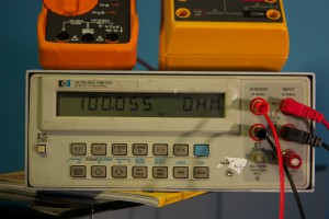
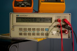
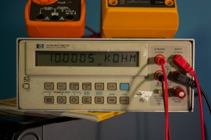
The second meter I picked up on Ebay for ~100$ + shipping. I was originally going to try and find another decent hand-held meter, but after seeing a review of the HP 3478A, I decided that I wanted to get a high-precision 5 1/2 digit (30000 count!) bench top meter. It can be found cheaper (I have seen it listed for 60$, but the auctions usually finish higher) but I figure if you can pick this bad boy up for less than 200$ shipping in, you’re doing good. This meter is old but an excellent purchase as the accuracy (as far as I can measure and test) is spot-on when compared against the Aglient meter. The basic DC accuracy of this meter is +/- 0.02% + 2 counts. Again, I have attached some shots of the HP meter measuring the same resistors as above:

IMG_5288 IMG_5290 IMG_5291

You will note that I used the 4-wire measurement function of this meter to measure these resistors. This allows the meter to remove any resistance from the test leads themselves (which ended up about a 2.5% error). Also, you may have noticed the “non-standard” test probe connector for the current measurement on the bottom right of the meter face: this was due to a the fuse holder/connector piece being missing (something I hadn’t noticed in the pictures of the meter on Ebay). I looked around, but even these HP meters being sold “for parts” were 100$+ and Agilent does not stock this part any more. I hacked on a binding post with a 3A fuse behind it and that solved that! So beware: when looking for this meter on Ebay or any other second-hand site, MAKE SURE you get the current socket + fuse holder!


Fluke 27/AN

The last meter that I picked up on Ebay is a Fluke 27/AN for ~70$ + shipping, although it can be found cheaper: I have seen them for as low as 50$ for this version.  It is the “worst” of the three: a 3200 count instrument, +/- 0.1% + 1 count basic DC volts accuracy. So it is more accurate than my Agilent (in theory) but has less resolution than the Agilent. The reason I bought this meter was to have a nice solid, built like a tank meter that I would be confident enough to use with mains testing (if need be) and would be rugged enough to use outside the “lab” environment. It also has a 10A current range, which is handy (since the HP can only handle a maximum of 3A). With a rated 900 hour battery life, this meter is the one that I would trust to be working when I need it. Below are some shots of the same resistor measurements as above:

IMG_5299 IMG_5297 IMG_5298


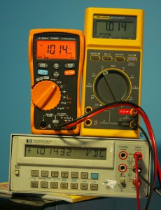
As a final test, here is a shot of all three meters connected to the same power source (DC voltage). As you can see, they are all almost exactly the same (of course the HP will have the most resolution, so we can ignore the least significant digits):

IMG_5285

All in all, for a couple of second-hand meters, I am very pleased with the overall accuracy (assuming that the Agilent I have is reasonably well calibrated, since I am using it as a transfer standard). I do not have a meter that can measure temperature, so that might be the next thing to look for!

MOSFET Driver Board, Rev C

It is said that one should learn from one’s mistakes. In the process of learning how to design and get a Printed Circuit Board (PCB) manufactured, I have indeed made a few mistakes. I would like to share them with you here.

First, a quick update on the board that I was designing. My requirement was to be able to drive a spinning light assembly (pictured below) from a micro controller (MCU). Rather than use the traditional relay-based system (which would use a transistor to achieve MCU control) I decided to design it using a MOSFET (a big ‘ol voltage-controlled switch). I also figured that this would present a good opportunity to learn how to design and lay out a very simple PCB.

Always, ALWAYS, Double-Check Your Work

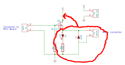
I don’t know if I can emphasize this more: a core theme in all of my mistakes during this project have been due to this. My first board, Rev ‘A’, suffered from a major circuit design error that occurred when I moved my circuit design from the bread board to the schematic CAD tool (I got the circuit backwards: I needed one that worked with a “NPN” transistor, but designed one that worked only with a “PNP” transistor).

Here is my awesome not working circuit (Rev A):

MosfetDriverBoard-RevA

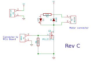
Here is the corrected circuit with the motor BEFORE the NPN MOSFET:

MosfetDriverBoard-RevC

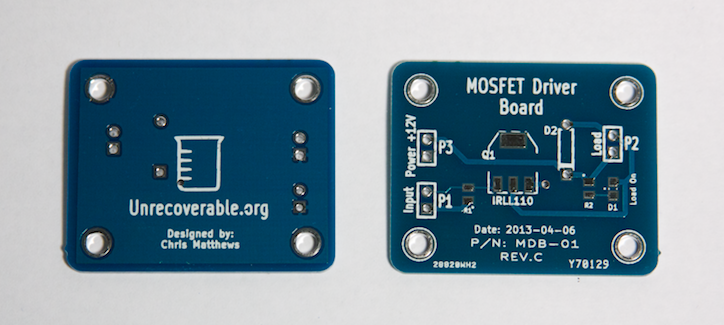
My second revision, Rev ‘B’, was not manufactured; it had the corrected circuit design, but I wanted to tighten up the physical PCB layout so I created Rev ‘C’:

IMG_5160

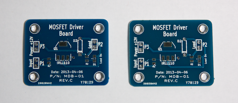
I had this revision manufactured. The mistake that I should have caught on this time was the adjustments I had made to the hole diameters for the terminals (for the inputs and outputs); I had forgotten to adjust the copper (called “annular ring”) around the holes to make them larger as well. This wasn’t a show stopper, as I was able to solder the components on the board still, but it was borderline.

As an aside, I noticed that the front solder-mask (the blue color) was not uniform between boards; some were blue and others were slightly blue-greenish, about half and half. I also noticed that the silk-screening was less than awesome on all the boards. Note that this board was Hot Air Solder Leveled (HASL) and NOT gold plated like the first revision board.

IMG_5158


Thou Shall Check The Data Sheet. Again.

The second biggest mistake that I made was not re-checking the foot prints (the “physical” sizing of a component) during and after I completed the layout of the PCB. DO THIS. It avoids embarrassing mistakes such as holes that are too small to fit the leads of a through-hole component. You should also re-check the pad/leads in the data sheets to make sure they fit with your component symbols and circuit design. Don’t assume anything!

Always Have a Reason

When you place a component, connect a trace, add a connection, always have a reason for doing so! This will prompt you to ask yourself why you are doing this and perhaps lead you to discover a mistake in the making.

Test Points

This board was a bit too small to warrant test points (PCB pads that are designed specifically to be accessible to probes for testing properties of your circuit) but remember to think about adding them in. This can make debugging a malfunctioning circuit much easier later on. Also remember that it may be a good trade-off when designing a prototype device to take a little more space but offer debugging facilities such as test points and wire jump points.

Remember To Add Your Name!

If you truly are happy with your design and PCB layout, then you won’t mind putting your name, date, revision information and other useful identification information on the PCB. Do it! This will make differentiating board revisions easier as well as identifying you as the designer. Take some credit!


Your ownCloud

After using Google Drive for a while, I realized that while it is nice to have your data available to the various machines that I use on a daily basis, I didn’t like the idea of someone else controlling access to my data. And especially since Google have a habit of axing perfectly decent applications. Enter ownCloud.

What is it?

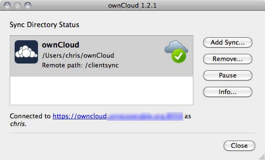
ownCloud-Status

OwnCloud is free open source software consisting of both client and server packages, and allows one to set up a rather nifty private “cloud” service (one can also rent accounts or even get a free account although I have not looked at either of these options too closely. There is more info on the owncloud.org website). Please note that there is ALSO a owncloud.com site that provides professional/enterprise services based on the OSS owncloud project.

Your Data on the Go!

To take it for a drive, I cooked up a new VM on my home setup and started playing around with the owncloud server software (written in PHP, so easy to install, questionably secure). The first thing I noticed was that this is not just a file-sync service; there is a web front-end which allows access to upload/download your files, and an application framework that allows developers to write applications that can take advantage of the cloud and sync functionality. But we will get into that a bit later. First, I present what the cloud should look like:

owncloud-weblogin

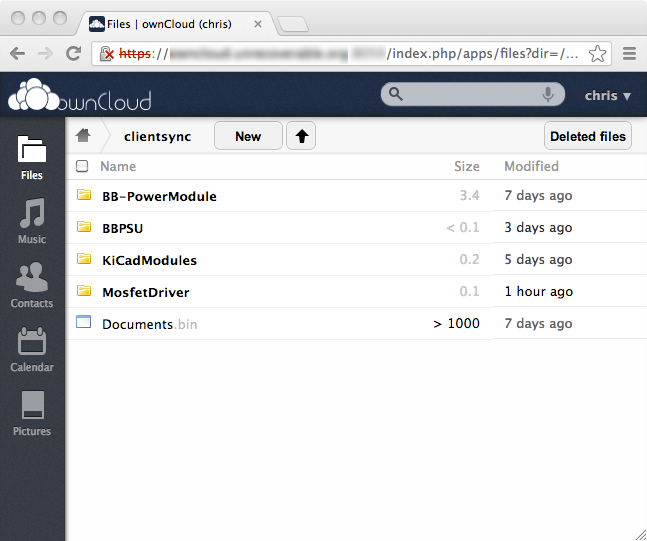
I created a quick SSL certificate to ensure that at least my data was accessed with at least a bit of protection. After logging in, one is presented with the file view:

owncloud-filesync1

Before this, I had already downloaded the owncloud client for the Mac, installed and placed a few files in the sync directory (by default this is: /Users/[username]/ownCloud):

owncloud-filesync3

I had already created an account on the my owncloud server so as soon as the client logged in, it began to synchronize the files on my Mac with the server:

owncloud-filesync2

Pretty neat!  I could also download these files directly from the web interface (nice), all files are versioned on the server (awesome) and owncloud allows you to either share files with another owncloud user on the same server, or provide direct URL links to particular files that you can send via email to someone (bonus!). These shared links also can be password protected and can have an optional expiration date for the share.

The second immediately useful app in owncloud is the calendar:owncloud-cal1

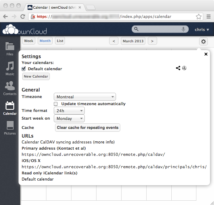
This calendar supports both standard CalDAV and Apple’s Calendar iCal formats as well as various configuration information:owncloud-cal2

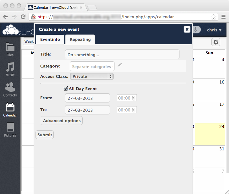
Creating an event in the calendar is very similar to many modern calendaring software packages (including Google Calendar):owncloud-cal3owncloud-cal4

Moving an event from one day to another works as one would expect, just drag and drop the event onto a different day.

Weird Behavior and Quirks

I did notice a couple of quirks, with the big one being that file size matters. I tried originally the same technique that I was using with Google Drive, which was: create an encrypted 2 GB partition file using Truecrypt, and then place my files in this encrypted container and synchronize that since file. This was a little bit of a pain with Google Drive, as even a small change to a single file in my encrypted partition would result in transferring the entire 2 GB file to Google Drive. OwnCloud had the same issue but worse: it would throw errors even trying to sync a 2+ GB file (there is a known bug open on this for owncloud). My recommendation would be to avoid using the file sync setup like I was above with large archive files; if anything keep your files small and separate.

As for the calendar, the single most annoying quirk was when event details were displayed, the scroll wheel acted on the main calendar screen instead of the currently open event. This was throughout the entire calendar app. It was very jarring to close an event and be looking at a different month.

Another annoyance is with the user interface in general: there is a general lack of feedback to the user if an operation succeeded or failed. Very annoying.

Conclusions

The overall feeling I get from owncloud is that it is decently written and works fairly well. Since it uses DAV for file transferring and versioning, I would recommend when choosing a server, give it some decent disk performance and CPU(s). The fact that there is an extensible application framework under the hood makes the design of owncloud very attractive as a central cloud data storage system. The interface is slick, works well enough although more feedback about the status of commands would be appreciated. Would I recommend it as an alternative to Google Drive or DropBox?  Absolutely!

Meet Public Key Cryptography: Asymmetric Encryption for the rest of Us

Most people in computing-related fields will have heard of public key encryption. The goal of this article to shed some light on how it works and how it is used. Most of the focus will be on providing explanations and examples that do not involve the mathematics of asymmetric cryptography.

Terminology

First we need to quickly define some terms that might be new to you.

  • Encryption: the act of taking a readable piece of text and transforming it into a scrambled, unreadable text. This operation is always reversible.
  • Decryption: the act of taking a previously encrypted text and transforming it back into its original readable form.
  • Plain Text: text that is readable by either humans or computers and not encrypted in any way.
  • Cipher Text: the output of some encryption algorithm. This text is (if the encryption is good) not readable by anyone or anything.
  • Key: an object used to open a lock. In cryptography, “keys” are used to transform plain text to cipher text and cipher text to plain text.
  • Public Key: a very large integer that is paired mathematically with a unique private key.
  • Private Key: a very large integer that is paired mathematically with a unique public key.

What is Asymmetric Encryption?

Imagine a box with a lock on it which we will define as a “lock box”. The typical lock box may have a number of identical keys, any of which can lock or unlock the box. This is how typical, or “symmetric” encryption works: one key is used to both transform the plain text to and from a cipher text. In asymmetric encryption, you have to imagine two keys and a single lock box. One key can only unlock the lock box (we will call this our “private” key), while the second key can only lock the lock box (we will call this our “public” key). To send a message, first distribute the public key to the person we wish to communicate with; we will call this person Alice. Now suppose Alice wishes to send us a message. She will compose her message, and place it in the lock box, shut and lock the box with the public key we have given her. The lock box will be sent to us, and we will then open the lock box with the private key that we have. The bit that makes this work is that the public key, which in theory could be given to anyone, can only lock the lock box. So any message that is placed in the lock box can only be viewed by someone with the matching private key. If we wish to send a message to Alice, we would need to have her public key and lock box and the same process would occur.

Details and the Devil

Unfortunately, no exact physical representation of asymmetric encryption exists (to my knowledge). A real asymmetric encryption system uses only a public key and a private key pair; the public and private lock boxes are not used. Furthermore, the astute observer will notice that a single public-private key pair were used to communicate only in a single direction. This is due to some properties of asymmetric cryptography.

Public Key Encryption

Suppose Alice and Bob wish to use asymmetric cryptography. They each have a public and private key, and they have both exchanged their public keys. Each can do the following:

  • encrypt a message with the others public key
  • encrypt a message with their private key

The previous example used the first case, where Alice used our public key to send us a message. This works because only our private key will decrypt the message, so the message is safely encrypted and only the recipient can read it. However, if we had wanted to send a message back to Alice such that no one else could read it, we could not use our private key to encrypt it, as anyone with our public key could decrypt and read the message. We must always assume that public keys are available to everyone and anyone (indeed we want this to be the case as we will see later on), and that private keys must be kept absolutely secret and is never distributed.

Public Key Signing

This property of anyone being able to decrypt a message that we encrypt with our private is actually useful, just not for exchanging secret messages. It can be used to verify that a message could only have been sent by a specific individual. For example, suppose we wish to send a message to Alice (perhaps our physical mail address) but we can not be sure that Mallory will not intercept the message and change our address for his. Assuming that Alice has our public key, we could simply encrypt our mail address with our private key and then send it to Alice. She will then be able to decrypt it with our public key and get our mail address. And what about Mallory? Suppose he finds a way of intercepting our encrypted mail address message (and don’t forget, he can decrypt it since we assume he could have access to our public key just as Alice does), replaces it with his own mail address, encrypts that with his own private key and then forwards it to Alice such that she thinks it came from us. Alice will then, believing that the message came from us, attempt to decrypt it with our public key. This will fail and result in garbage since our public key will not decrypt Mallory’s message. Alice will then know that the message did not originate from us and will not trust the mail address that she received.

In Real Life

Asymmetric encryption is rarely (if ever) used to encrypt or sign whole messages; the computation cost is too high. For encryption, a symmetric key (remember that symmetric encryption uses a single key for both encrypting and decrypting, much like a physical key and lock) is generated by the sender (this is sometimes called a “session key” since it is usually valid only for the immediate message being exchanged between two individuals), and used to encrypt a message. The session key is then encrypted with the public key of the recipient and sent to the recipient along with the encrypted message (Note that these session keys are almost never sent between two parties over the wire; protocols like Diffie-Hellman key-exchange perform this function in a more secure fashion for interactive communications). The recipient will then decrypt the session key with their private key and will now be able to decrypt the message . Symmetric encryption is used to encrypt messages because they are very very fast when compared with asymmetric encryption and messages are typically fairly large (typical “large” keys are 1024 bits or 128 bytes versus messages that are typically greater than 512 bytes).

For signing, a hash of the message being sent is encrypted (or “signed”) with the private key of the sender. A hash is a one-way function that maps a block of data (the message in this case) to a unique numeric value. The message and signed hash are then sent to the recipient, who will then re-hash the message, and compare it to the decrypted hash (signature). If they match, then that message was sent by the sender.

Problems

There are a few problems with asymmetric encryption. The most glaring problem is how does an individual know that the public key they have actually belongs to who they think it does? This seems trivial; one just has to be given it by the owner of the public key. However, in real-life we may not know the recipient of a message or have had any prior contact with them before we wish to send them a message. This is where Public Key Infrastructure (PKI) comes into the discussion. This is a system that provides a mechanism for the distribution and storage of public keys. Key exchange is a complicated problem (and far, far outside the scope of this article), and there exists no fool-proof scheme that is convenient enough for the general public to use at this time.

Another major hurdle to adoption for this type of encryption and signing was hinted earlier: there is no good physical representation of asymmetric encryption, and so it is difficult for individuals to grasp how it actually works and how to use it correctly.

But perhaps the biggest problem with this (and many other forms of encryption) is that people don’t feel that their email to grandma is important enough to warrant the added complexity encryption brings. This view is changing slowly; until fairly recently the whole idea of “encrypted” web sites (such as your bank’s web site for example) was very abstract for the general population.

Conclusions

Asymmetric encryption serves two primary purposes: to encrypt messages and to sign message. For bi-directional communications, each participant must have their own public and private keys, and must have the public key of every participant that they wish to communicate with. Messages are never encrypted with asymmetric keys; they use a symmetric (session) key instead. Hopefully this article provides a bit of clarity on how asymmetric encryption technology can be used to aid in secure and trusted communication.

References