HP8642B Signal Generator Mod

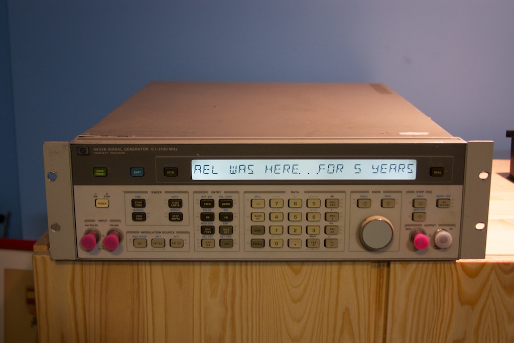
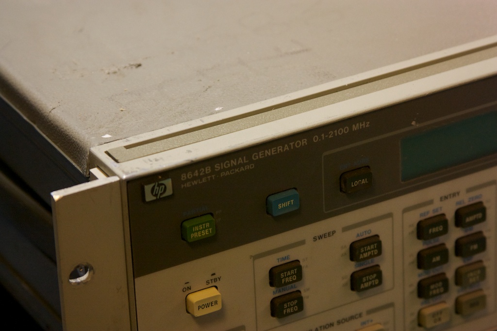
A quick mod post here. I saw this post by Kerry Wong, and having the same hardware myself (and finding the backlight ridiculously dim) I thought this mod was a great idea and wanted to try it myself. First, here is a shot of the original backlight:

HP8642B-OrigBL

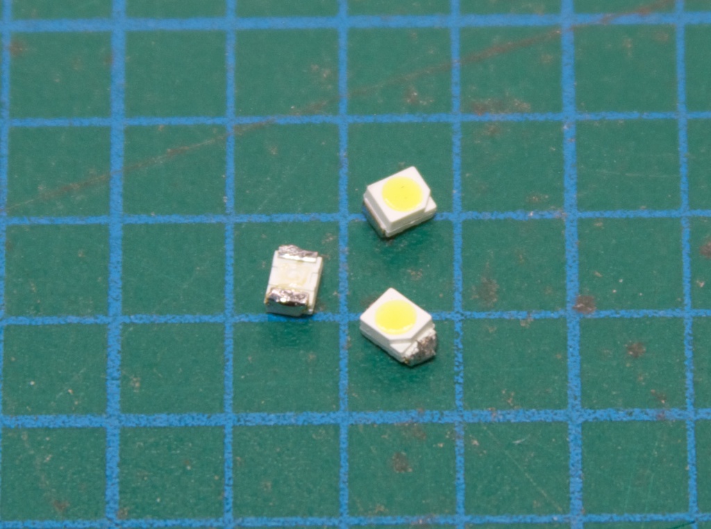
I pulled the front panel apart, and decided to use white SMD LEDs for my replacement mod:

IMG_5664

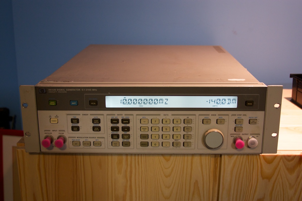
After soldering up everything and reassembling (and of course cursing a lot due to the number of defective white LEDs that I didn’t realize that I had), the result is beautiful!


HP8642B-Mod

And here is the same Easter egg that Kerry found (hold down the MSSG key while powering on the unit):

HP8642B-ModBL1


Function Generator Shenanigans

So my problem turned out to be not the saving of the status of the HDG2002, but actually doing the following:

  • Go to Utility, select System Status
  • Toggle the “Startup” option to “Last” (to set the function generator to restore to the last setup before power-off I assumed!)
  • Exit back to the main channels screen
  • Power Cycle the generator using the power button on the front panel.

When the HDG2002 reboots, POOF! No more main screen after the Hantek logo briefly flashes on screen. So what happened? It turns out that the problem is actually that the BACKLIGHT is set to level 0 by doing the above procedure. I found this out by logging into the serial console and finding the /dso/app directory. In here, there are a couple of “test” binaries:

test_beep
test_bkl

I tried them both but the test_bkl was the interesting one. When I ran it with the following options:

./test_bkl on 105

Poof the display popped back on! Of course on reboot it turned back off again. So after temporarily re-enabling the backlight, I went back into Utility -> System Status -> Startup and set it to Default, power cycled and boom, back in business no worries.

Well I guess there are still a few bugs in the firmware.  Please note that you can run into this bug REGARDLESS OF WHETHER YOU CRACK THIS FUNCTION GENERATOR OPEN OR NOT, and it has nothing to do with modifying the HDG2002. Except that if you don’t crack it open after you do this, you seemingly have no way to recover.

Hope this helps someone else!

Signal Generator

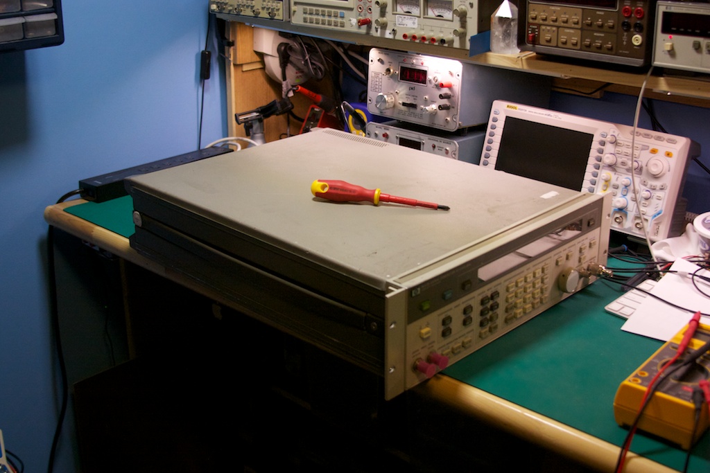
This is an acquisition that I purchased earlier in the year (a great bargain off EBay!).

IMG_5570

I decided to have a look inside it (not having any clue what goes into a function generator of this caliber.

IMG_5569 IMG_5572

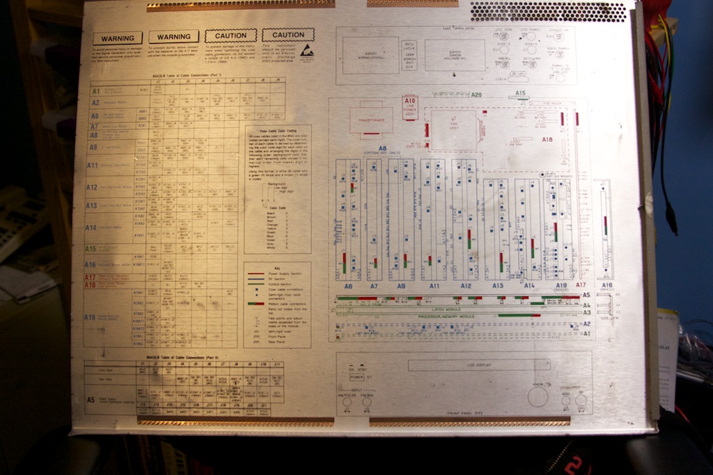
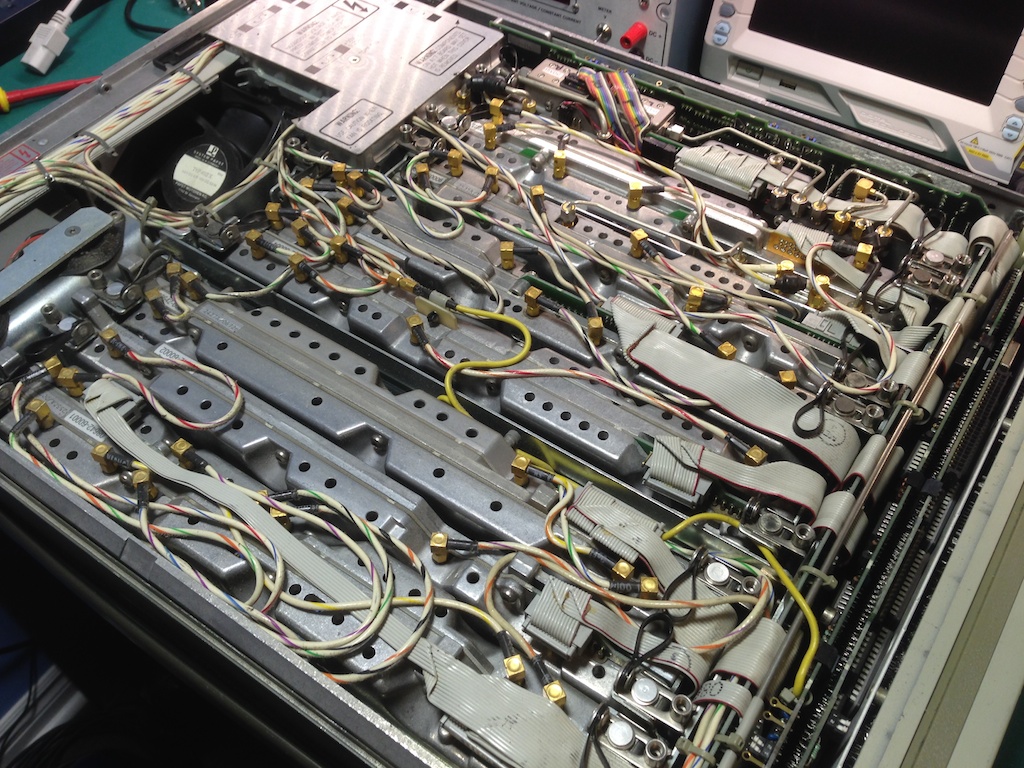
Nice idea of putting the wiring schematics on the cover of the unit, as that way one can always figure out how to put the whole thing back together. And then I saw this:

IMG_0807

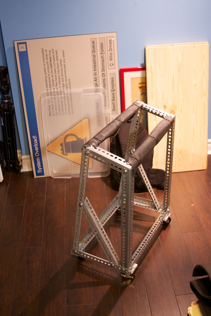
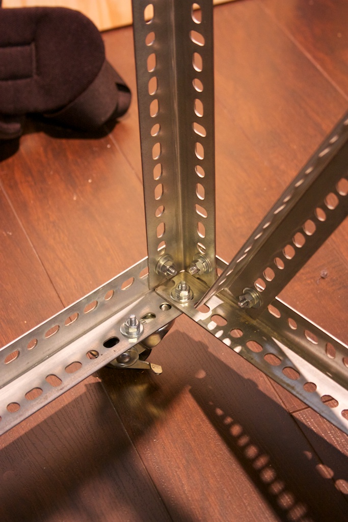
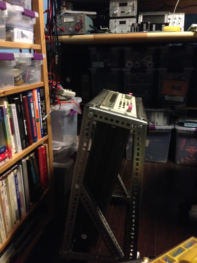
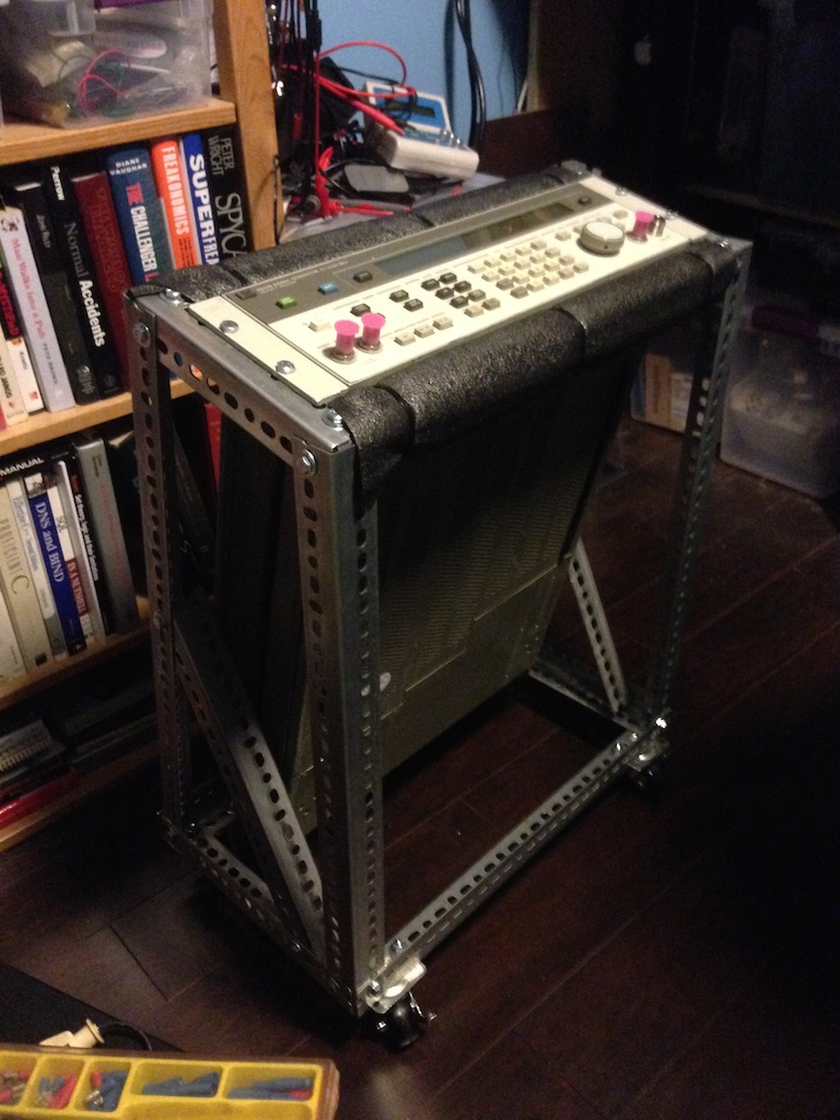
Wow.  So I decided to save a deeper dive into the unit for a later date. I built a stand for the generator and called it a day.

IMG_5574 IMG_5576 IMG_0810 IMG_0809

Lab Frequency Standard

I’ve been rather silent for a couple of months now, but I have been busy! This time it is a laboratory frequency standard! This project is modeled on the work done by Gerry Sweeney over on his blog. I have been assembling the various pieces needed for this build for several months now, and just recently decided to take the plunge and do the build.

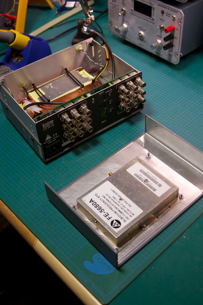
It started off with a Rubidium frequency standard from Frequency Electronics, the FE-5680A. These can be purchased used off of EBay for ~120$ CAD. Buyers beware: I had success with my first unit, but others have not been so lucky. There are numerous configurations of this unit, with various features present or missing, including the 10MHz sine output. This project requires at a minimum the 10MHz out. Some units will have this via a dedicated BNC or SMA connector, others (like my unit) will have it present on a pin from a DB-9 connector.

The second most important component is the case which will house the completed project. I was originally going to choose a basic project box, but Gerry was pointed towards a distribution amplifier for video. Since the signal from the FE-5680 would need to be replicated on multiple outputs to be useful, some sort of amplifier was going to be needed. It just so happens that 10MHz lies in the range of off the shelf video amplifiers, and the model I got by Extron, the ADA 6 Component was perfect for the job AND was only 40$ on EBay.

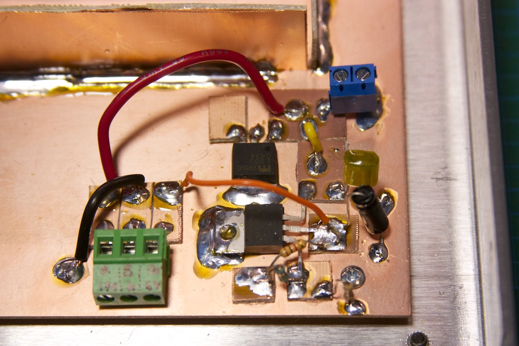
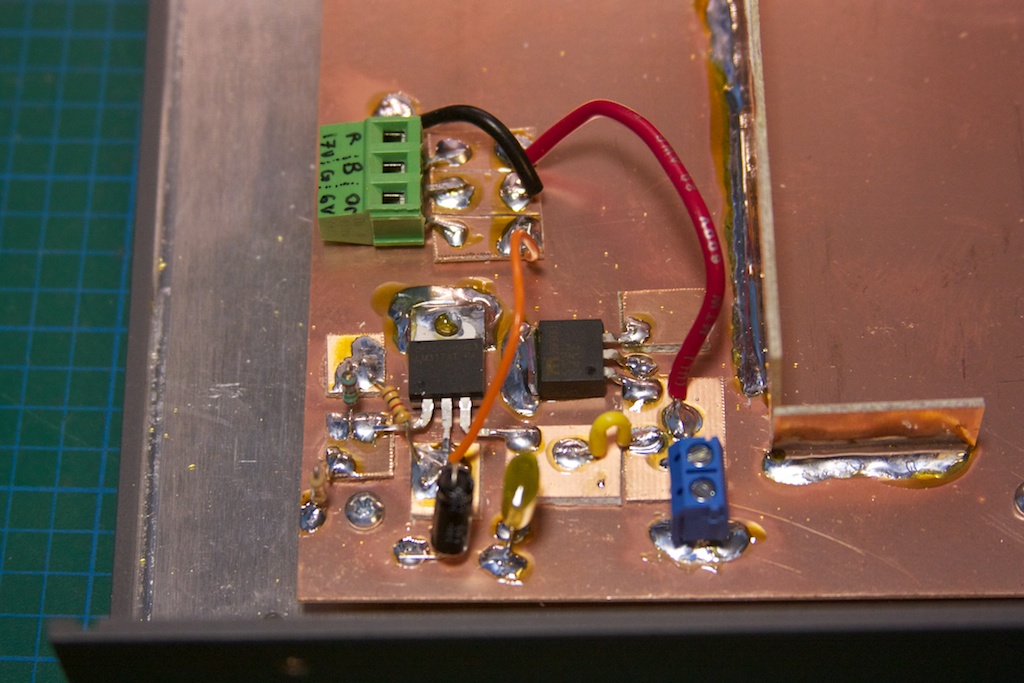
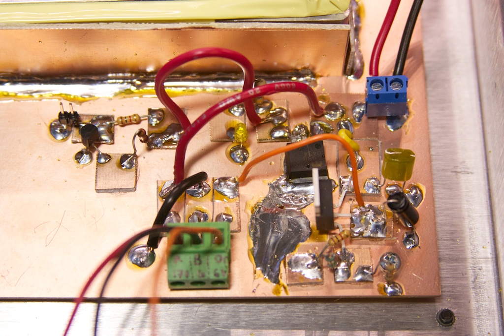
Other than just putting the Rb standard in a box with a bunch of outputs, I wanted to have an indicator LED that lit up when the Rb was locked on 10MHz. My particular unit will pull a pin on the DB-9 connector LOW when the Rb is locked. A quick transistor circuit with a regulator feeding off a 17V supply and I had a small prototype board completed:
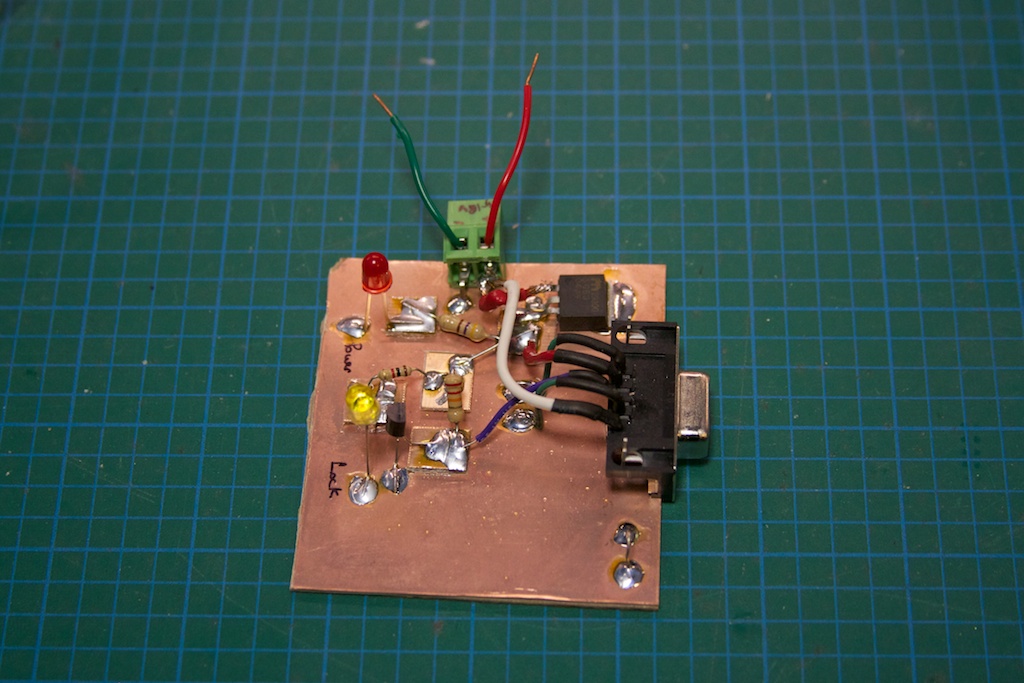
IMG_5579

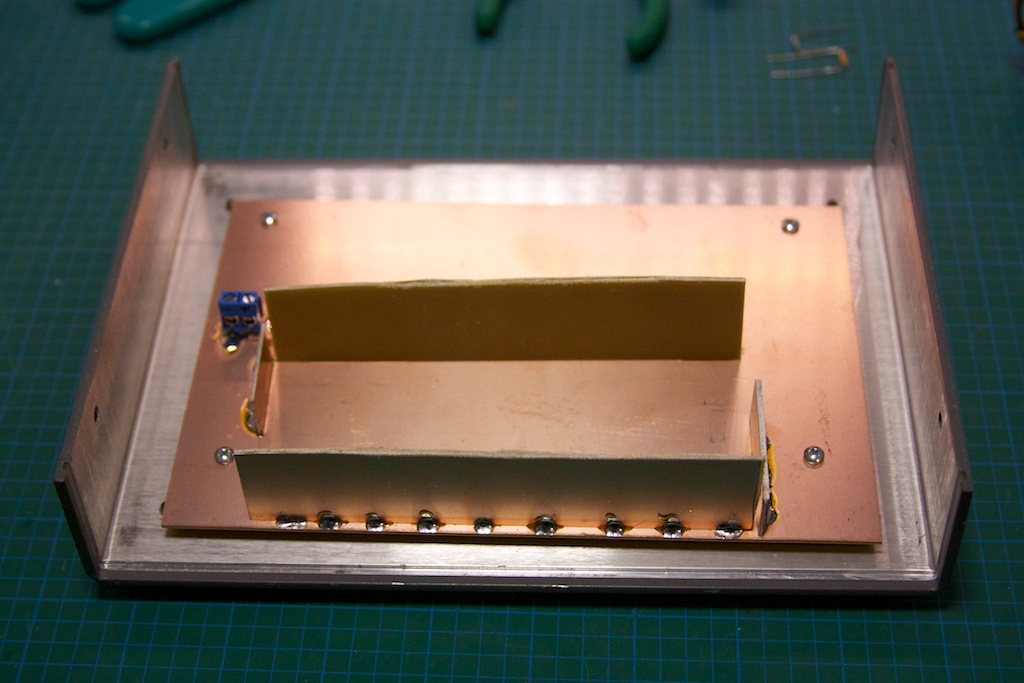
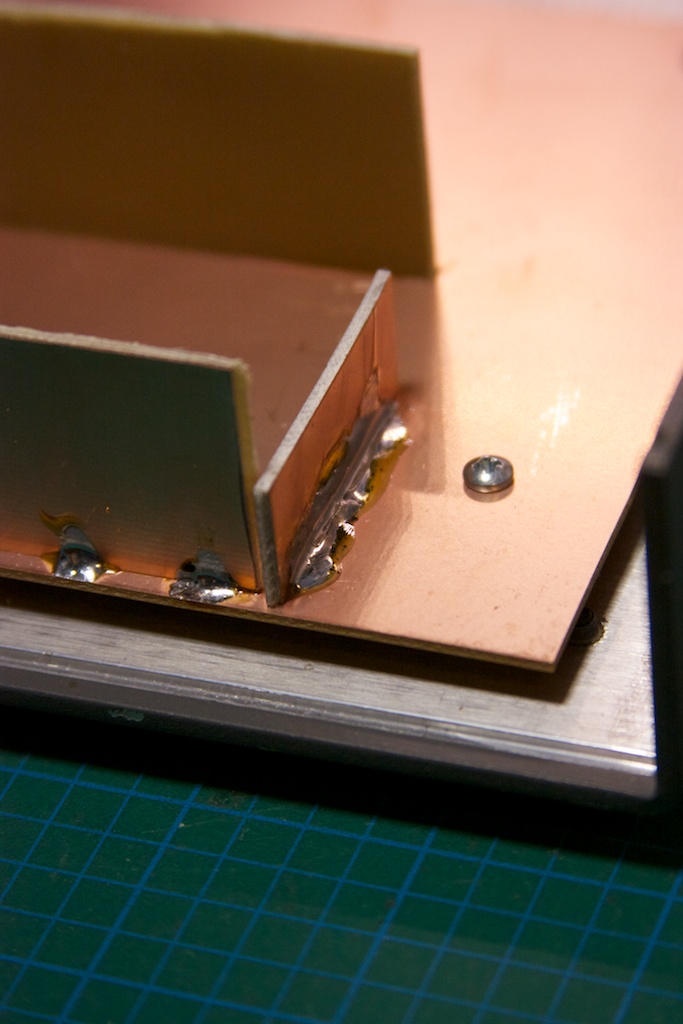
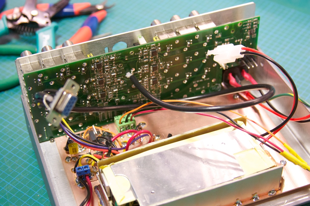
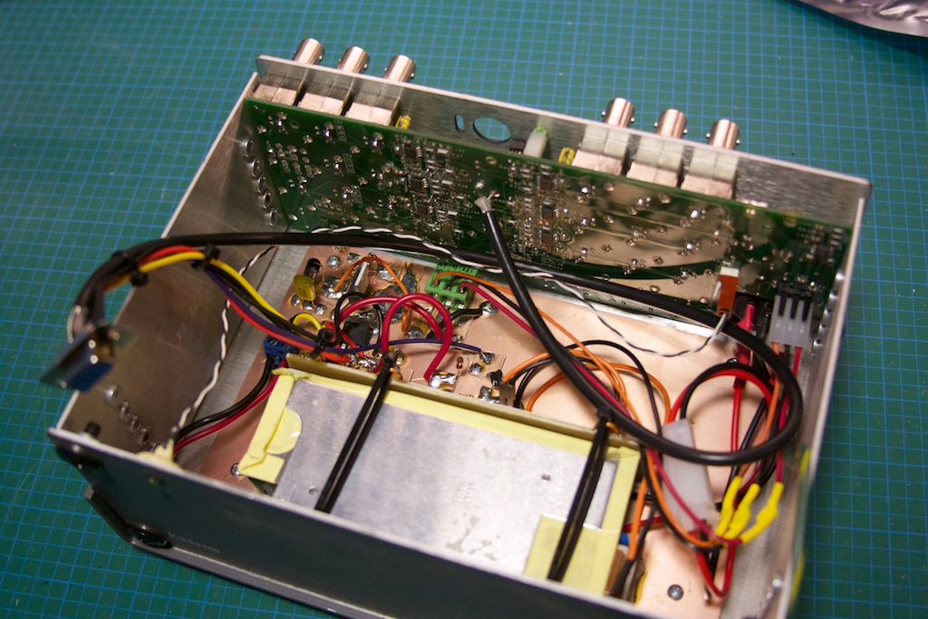
Once I had the “interface circuit” figured out, I started laying out what the mechanical construction of the project would look like. I decided to use the case itself as a heat-sink and seeing as how the Rb standard likes to be warm (haha, non-heat-sinked, the case measures ~65C), I decided to mount it to the top half of the box:
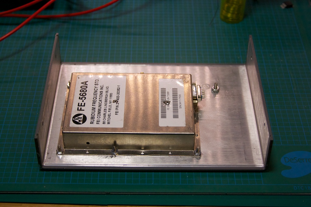
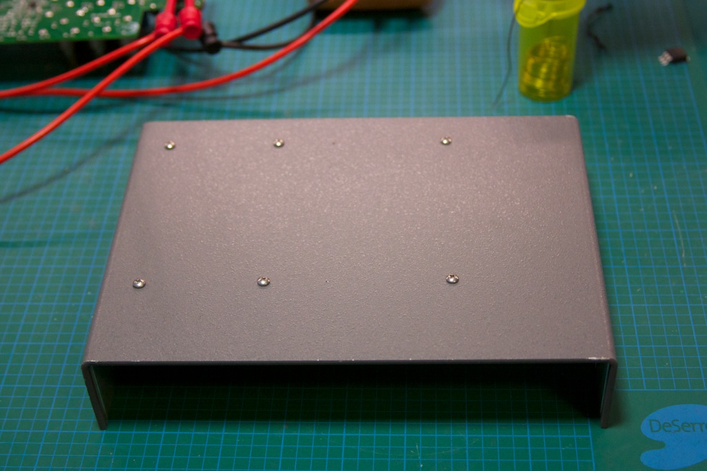
IMG_5577 IMG_5578

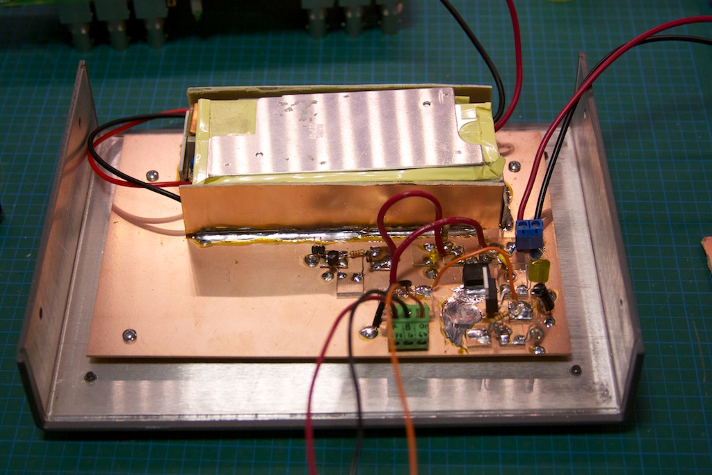
The Rb standard requires 2 different power inputs: 5V and15-18V. The distribution amplifier also required 2 different power rails: 6.2V and 17V. I decided that the easiest way to power it all would be to pick up a 18.4V laptop power brick, rip the guts out, and add a LM317-based regulator to get the 6.2V to my existing interface circuit. I discovered that the Extron was actually using the 17V rail to power a buck converter-inverter circuit, so the 18.4V input didn’t change it too much.
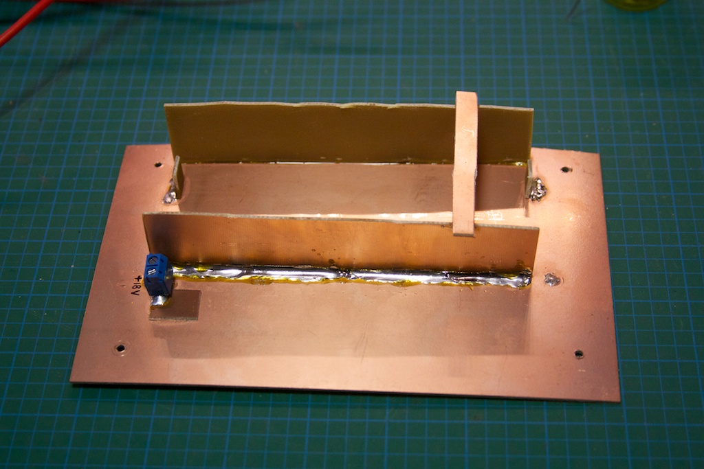
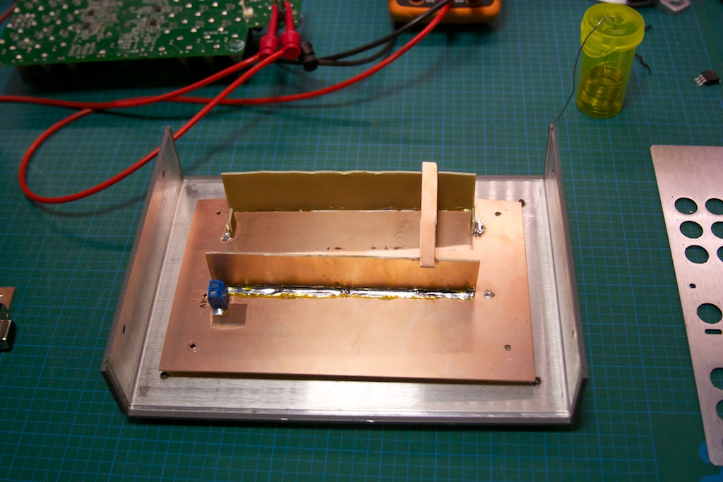
IMG_5580 IMG_5581 IMG_5585 IMG_5587 IMG_5588 IMG_5589 IMG_5590 IMG_5591

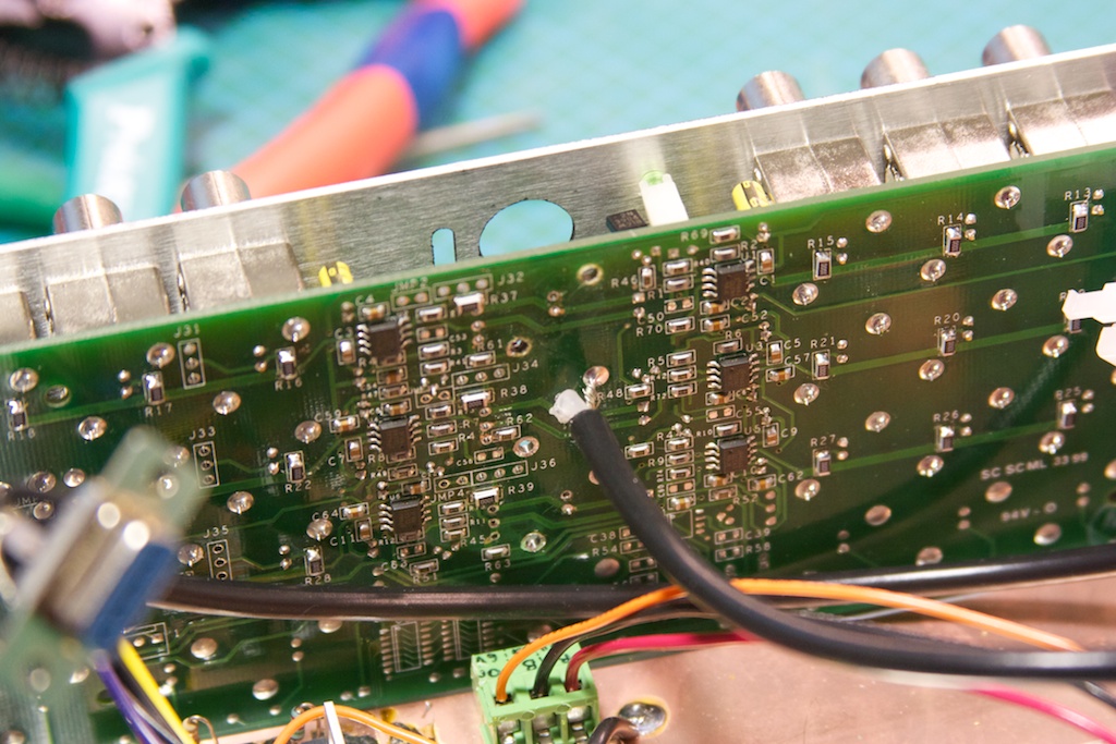
I wired up a small wiring harness to go from the Rb standard’s DB-9 connector to the various parts of the interface board. I then modified the amplifier board to change the input/output impedance from 75ohm to 50ohm:
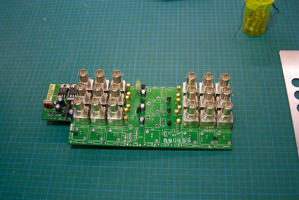
IMG_5582

Not having any 50ohm resistors handy (and they’re damn expensive as well!), I used 2 100ohm resistors in parallel stacked on top of each other:
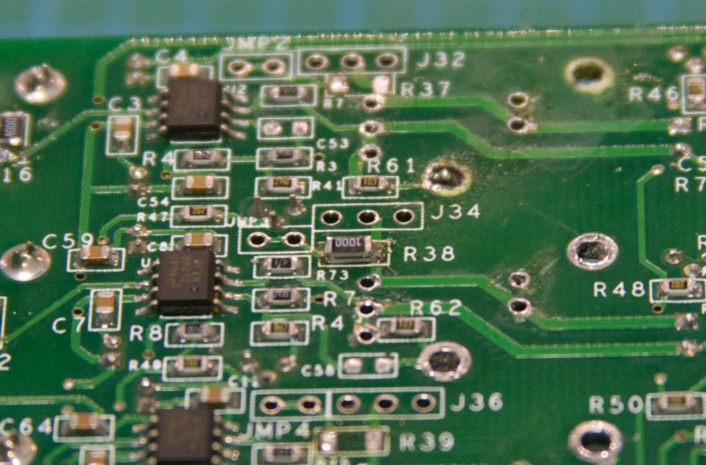
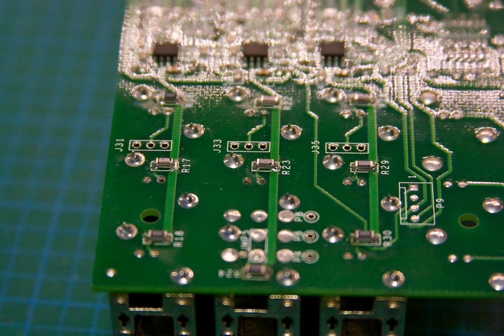
IMG_5584 IMG_5583

I soldered in the coax to the center channel, and then jumped the signal from the center channel to the 2 other ones with some wire. This means I will have a total of 18 10MHz outputs on this standard 🙂

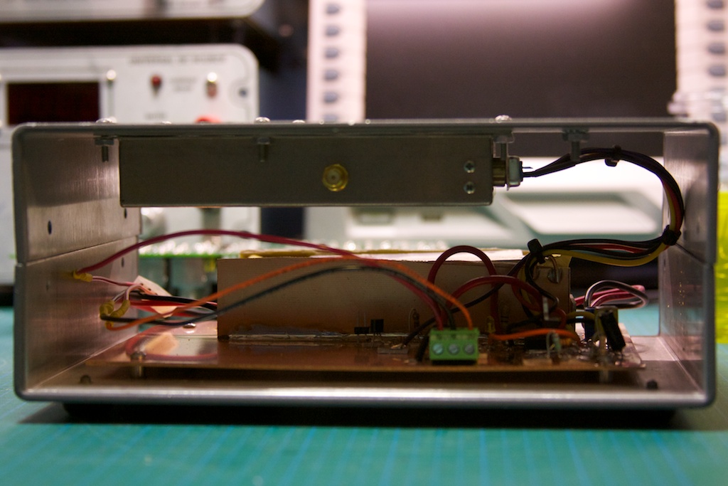
The testing and assembly:IMG_5593 IMG_5597 IMG_5598 IMG_5600 IMG_5601
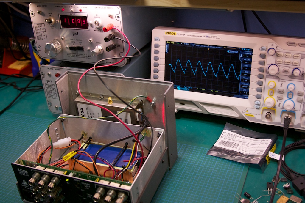
I ran into one problem when testing, which was a deformed lower part of the sine wave on the outputs (all of them). You can see it on the oscilloscope to the upper right:
IMG_5602

I started probing around (“THOU SHALL CHECK VOLTAGES!”), and discovered that the negative rail to the op-amps was running at ~0.3V, which was not right. Running back through the circuit on the amplifier board I realized that I had flipped the 6.2V and 17V rails on the input connector after splicing it into my interface board. After switching them back, everything was working as expected!
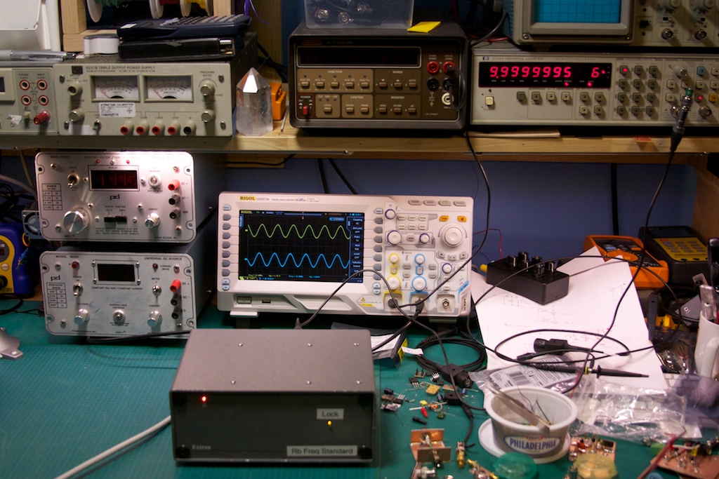
IMG_5604

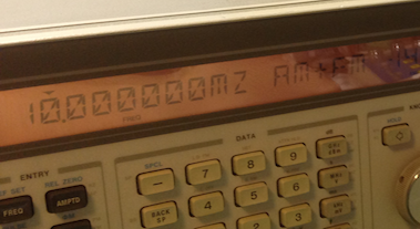
Turns out my frequency counter on the upper right is probably off by 0.5 Hz… not too shabby. There are a couple of things that need to be done: adding a heat-sink to the top of the case for extra dissipation and adding some passive ventilation holes on the top/back of the case and on the bottom.

New Threat On The Block

I know many of us run Windows and perhaps have home networks, etc etc. I also figure that a few of you have at least one important document that may not be backed up. There is a “new” nasty virus out in the wild, called Cryptolocker.

What is it?

This virus seems to spread via email and is a Windows (for now) executable file that you have to run on your computer. Once this happens, this virus starts to encrypt all of your documents (a fairly complete list is in the link below) with a VERY secure key. It can also encrypt all document files of other users on the system if the account that it is running as is an Administrator user. It will also try to encrypt all files it finds on mapped network drives.

After this is finished (and you don’t get a helpful pop-up saying it’s doing this BTW) it will prompt you to pay a certain amount (I think it is 300$ USD or something) for the decryption key and it will start a timer count down. If you don’t pay up by the time the counter hits 0, it will remove itself and any possibility of recovering your files (it keeps the key that is required to decrypt your files on a random remote server).

How do I prevent being bitten by this thing?

Funny enough, the solution is rather simple: back-up your data to an offline location (external hard disk for example). Do not use a “cloud”-based online backup solution as they will typically over-write your good files with the encrypted versions. So avoid a disk imaging style back-up; this will just result in you backing up your encrypted files before you know you have the virus.

What do I do if I get it?

No, that anti-virus software isn’t all that useful (at least not yet) since many (if not all) AV software vendors have yet to update their software to protect against this virus. The only way to get your data back for the moment is to pay the ransom. If you DO get hit with this thing and you intend to pay the ransom:
  • DO NOT MOVE OR TOUCH ANY OF THE ENCRYPTED FILES; otherwise even with the key the virus will not be able to decrypt your files;
  • DO NOT install or update your anti-virus software; the current few that recognize this virus will simply remove it, along with the key that you would need to decrypt your files and any chance of you getting your data back.

If you would like more detailed (read: technical) information, please have a look at this thread:

http://www.reddit.com/r/sysadmin/comments/1mizfx/proper_care_feeding_of_your_cryptolocker/


New Power Supply

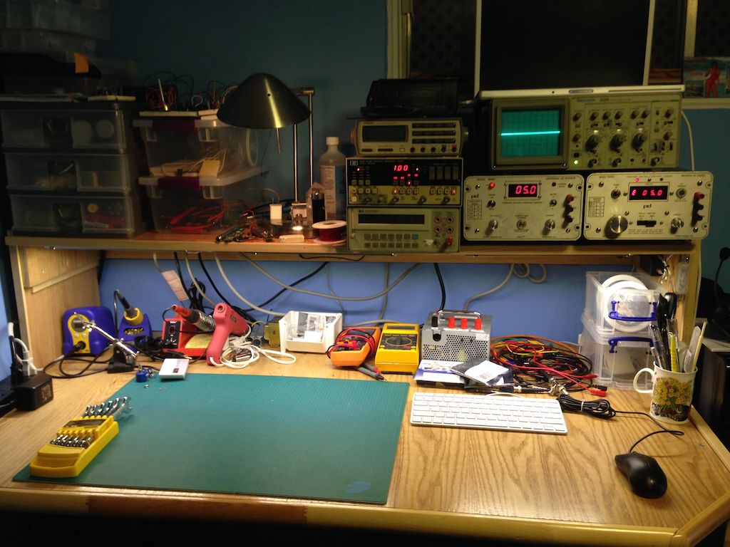
One can never have enough power, and in even a small hobbyist electronics lab, one needs at least 2 supplies (to generate both positive and negative voltages simultaneously). The Power Designs supply that I first bought I liked a lot: fairly cheap on Ebay (~75$ shipped), 0 to 60V linear range (no range switching), has a max load of double its rated load and has a current limiting feature (important so as not to break your awesome devices under test!).

IMG_0460

Compilers Never Lie

Just a quick note about an annoying behaviour I found in the Ardunio IDE + compiler + toolchain. I was writing the following task scheduler and started off with the typical typedef of a function prototype:

typedef void (*callback_t)(void);

struct task_t {
 long interval;
 int lastScheduled;
 int nextScheduled;
 boolean oneShot;
 callback_t callback;
};

void setup() {
}

void loop() {
}

void addInterval(int intervalMicros, callback_t f) { 
}

void addOneShot(int delayMicros, callback_t f) {
}

This kept on throwing the following compilation errors in the IDE:

Scheduler:6: error: 'callback_t' has not been declared
Scheduler:7: error: 'callback_t' has not been declared

Weird, since there’s not even a USAGE of callable_t on those lines.  Sniffing a bit deeper, I found that the IDE actually pre-compiles my program (called a “sketch”) into a temporary .cpp file, which contained the following:

#line 1 "Scheduler.ino"

#include "Arduino.h"
void setup();
void loop();
void addInterval(int intervalMicros, callback_t f);
void addOneShot(int delayMicros, callback_t f);
void run();
#line 3
typedef void (*callback_t)(void);

struct task_t {
 long interval;
 int lastScheduled;
 int nextScheduled;
 boolean oneShot;
 callback_t callback;
};

void setup() {
}

void loop() {
}

void addInterval(int intervalMicros, callback_t f) {
}

void addOneShot(int delayMicros, callback_t f) {
}

Ah ha! The damn sketch “pre-compiler” was automatically forward declaring my two functions addInterval() and addOneShot() and this was creating an undefined forward usage of callback_t. Thank you Arduino IDE.